
Astro-Egg Lander
On 6 April 2013, YUAA won the Astro-Egg Lander event at the Battle of the Rockets Competition in Culpeper, Virginia. The Astro-Egg Lander (AEL) team designed and built a rocket and lander capable of launching an egg to 1,500 feet and recovering it safely without using a parachute. The team’s rocket, the YSS Eli Whitney, flew six times, including both test and competition launches. At the competition, no other team managed to both recover their egg and reach an altitude sufficiently close to the target. By doing both, the YUAA Astro-Egg Lander Team brought home a shiny plaque and pride in a job well done.
Battle of the Rockets
Each April, undergraduate and high school students from across the USA travel to Battle Park in Culpeper, Virginia to compete in Battle of the Rockets. The competition consists of three events that change each year.
In 2013, YUAA fielded two teams competing in separately judged events. Competitors in Target Altitude had to launch a rocket to a height as close as possible to a specified target, while the Astro-Egg Lander event required that the rocket deploy a lander to carry a Grade A egg safely through a controlled descent without using a parachute.
Battle of the Rockets is sponsored by the Federation of Galaxy Explorers and the Tripoli Rocketry Association.
Objectives
Winning the Astro-Egg Lander competition meant solving four core design challenges:
To build a lander capable of slowing an egg’s descent to under 30 feet per second without a parachute.
To incorporate a protection system into the lander to prevent the egg’s breaking in setup, launch, flight, descent, impact, or retrieval.
To build a rocket capable of carrying the egg-laden lander as close as possible to exactly 1,500 feet using a motor classed no higher than J (1,280 N·s total impulse) and returning to the ground undamaged.
To deploy the lander from the rocket at apogee.
Lander
Because the competition did not allow parachutes for the lander, the team considered balloons, gliders, and retro-rockets before choosing an auto-rotator design. As an auto rotator, or autogyro, descends, the air moving past its blades causes them to spin, providing lift.
Over many tests, the team developed a design with four blades attached to a central rotor head. The rotor head contained an altimeter and battery in its top and a rod holding the Egg Protection System attached to its underside. A clear plastic lid protected the electronic components. Blade couplers allowed each blade to fold 90° to fit inside the rocket, with elastic bands attached to the rotor head pulling them upright upon deployment.
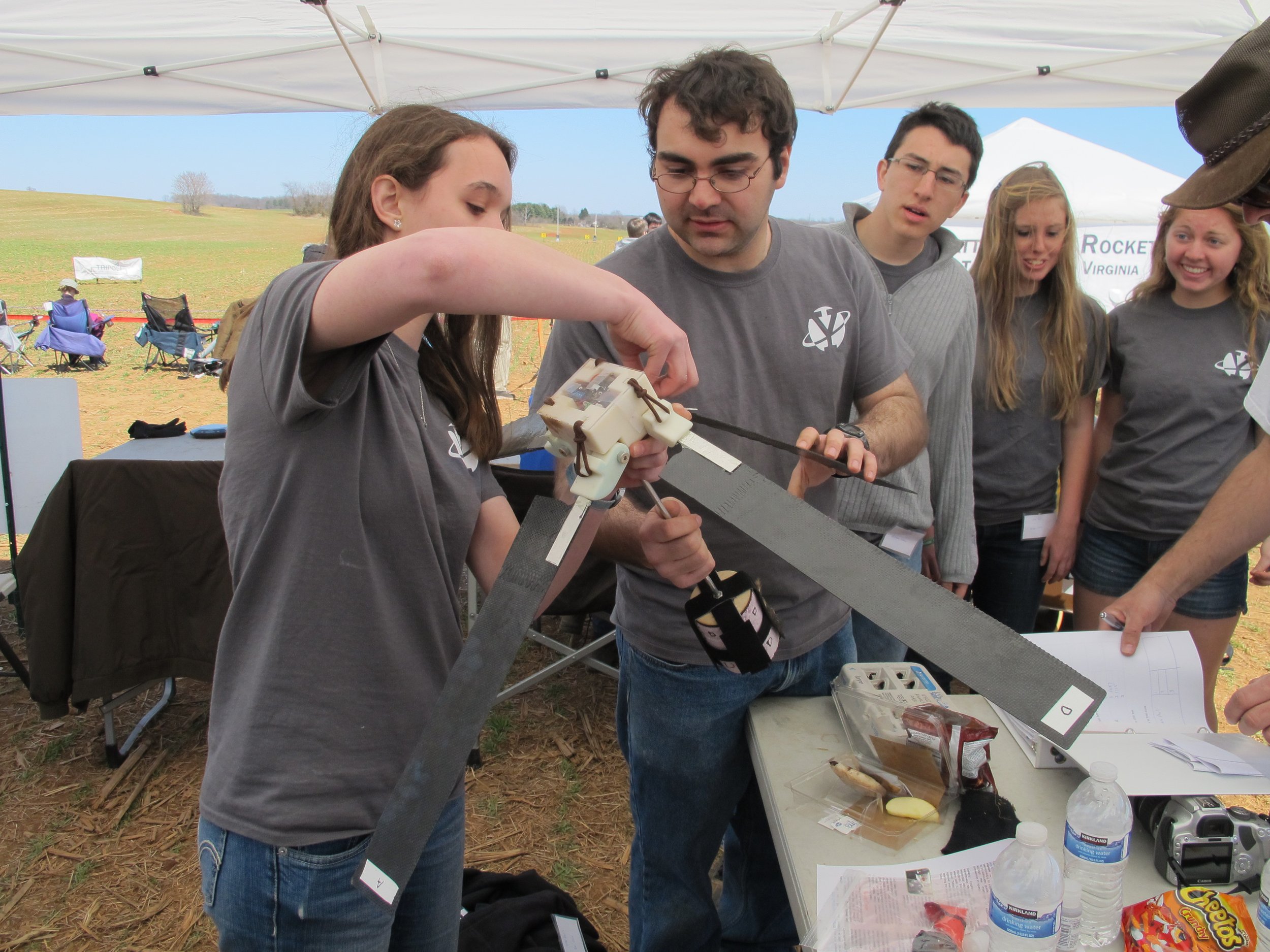
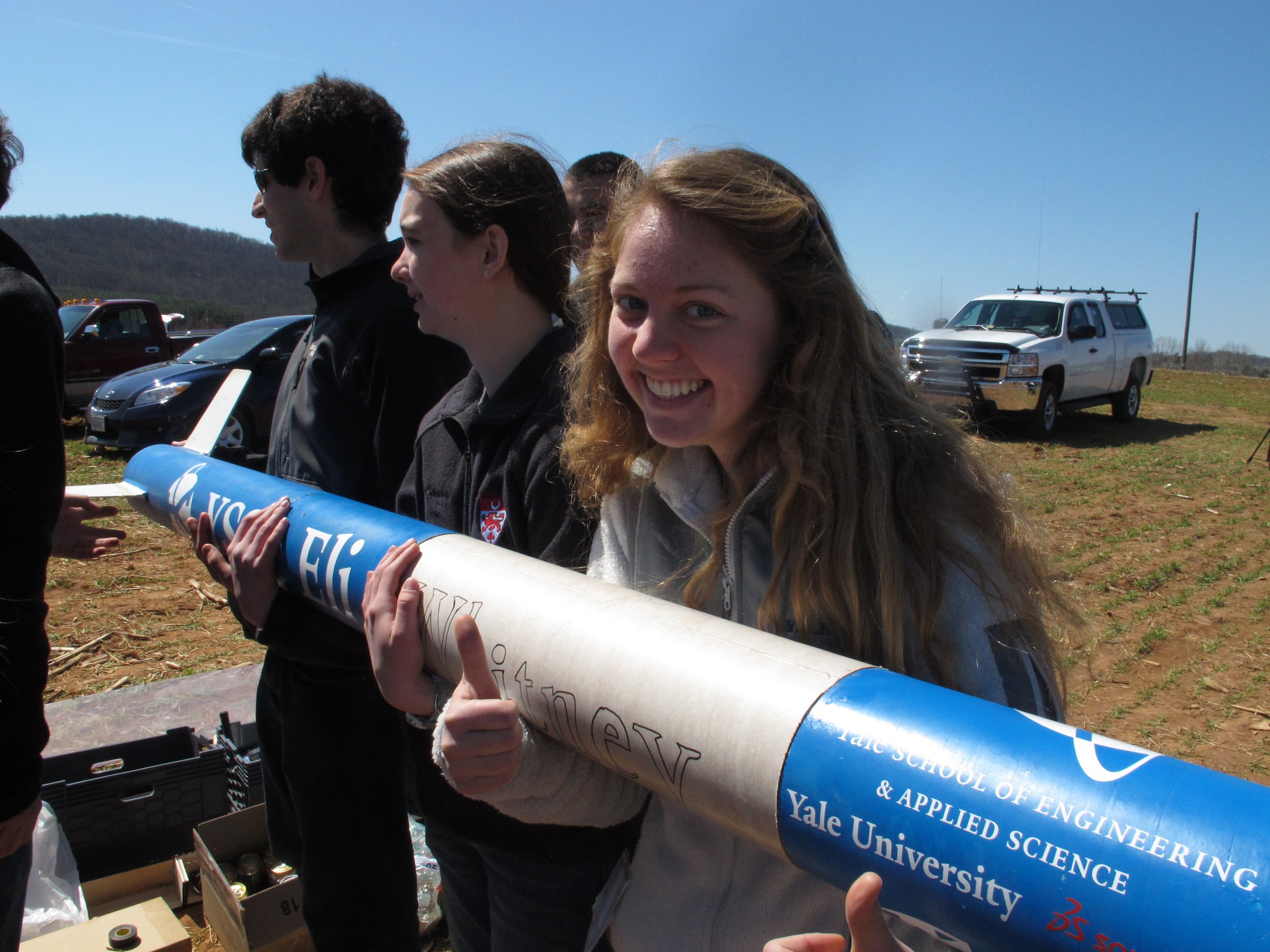
AEL members bringing the lander to the competition judges
The rotor head at the lander’s core had to be made strong to endure rotation, light to ensure stable flight, roomy to hold electronics, and compact to fit in a rocket. Early prototypes, simple foam blocks with angular slits cut to hold stationary wooden blades, helped the team test rotor designs. After investigating elastic rubber joints for folding the blades, the team rejected the material as too likely to twist under the torque from turbulent airflow and deform under persistent stress.
Using SolidWorks, Bolun Liu prepared the final design consisting of a central hub with four blade couplers able to freely rotate on shoulder screws. The rotor head had cavities for a PerfectFlite Stratologger altimeter with a 9V battery, switch, and wires; a slot for a ball bearing on the underside; and grooves for attaching elastic bands to the blade couplers.
All rotor head parts were printed on a Dimension 3D printer. During a test launch, the first model, printed at low density, broke into five pieces as the lander spun. For this reason, the rotor head used at the competition was printed at high density, even though the added weight unbalanced the aircraft.
The lander used rotor blades made from carbon-fiber-reinforced polymer (CFRP), a composite made strong by carbon fiber and rigid by epoxy. CFRP neither cracks nor twists easily with the high strength to weight ratio needed to endure fast rotation.
AEL team members made the blades by cutting carbon fiber into 18″ by 2.5″ strips, coating the strips with epoxy, and layering them in stacks of five. After the blades had dried for 24 hours, their edges were sawed and sanded.
CFRP has disadvantages: carbon fiber and epoxy are not only expensive but also potentially hazardous. Carbon fiber particles can irritate the skin and upper respiratory tract, and epoxy fumes can inflame and sensitize the nose, throat, and lungs. We worked with these materials only in ventilated spaces while wearing protective clothing including a dust mask and gloves.
Egg Protection System
The team’s first Egg Protection System (EPS) designs were shaped like a cone or bowl on the theory that their pointed or curved bottoms would absorb or deflect enough energy to protect the egg. Unfortunately, dropping these prototypes from even a single story only splattered the pavement. Further trials suggested that a design that held the egg completely immobile might produce better results.
The team tested a variety of prototypes based on this rationale, including a cup filled with honey to provide viscous resistance to the egg’s motion on impact, an array of toothpicks arranged to provide a crumple zone around the egg, and a box of insulation foam carved to hold the egg in place. Of these designs, the foam alone proved successful. As confirmed by additional tests, it distributed the pressure of impact evenly enough to keep the egg from cracking.
To build the next model, the team changed the foam’s shape to a 3-inch-diameter cylinder able to fit comfortably within the rocket tube’s 5.38 inch inner diameter. Upper and lower halves, each 2 inches tall and held to each other by removable Velcro strips, encased the egg inside precisely-carved sockets. A metal rod attached the EPS to the rotor head. After a test in which the rod punched completely through the EPS, nuts mounted on wooden plates were added to the upper cylinder to hold the rod in place.
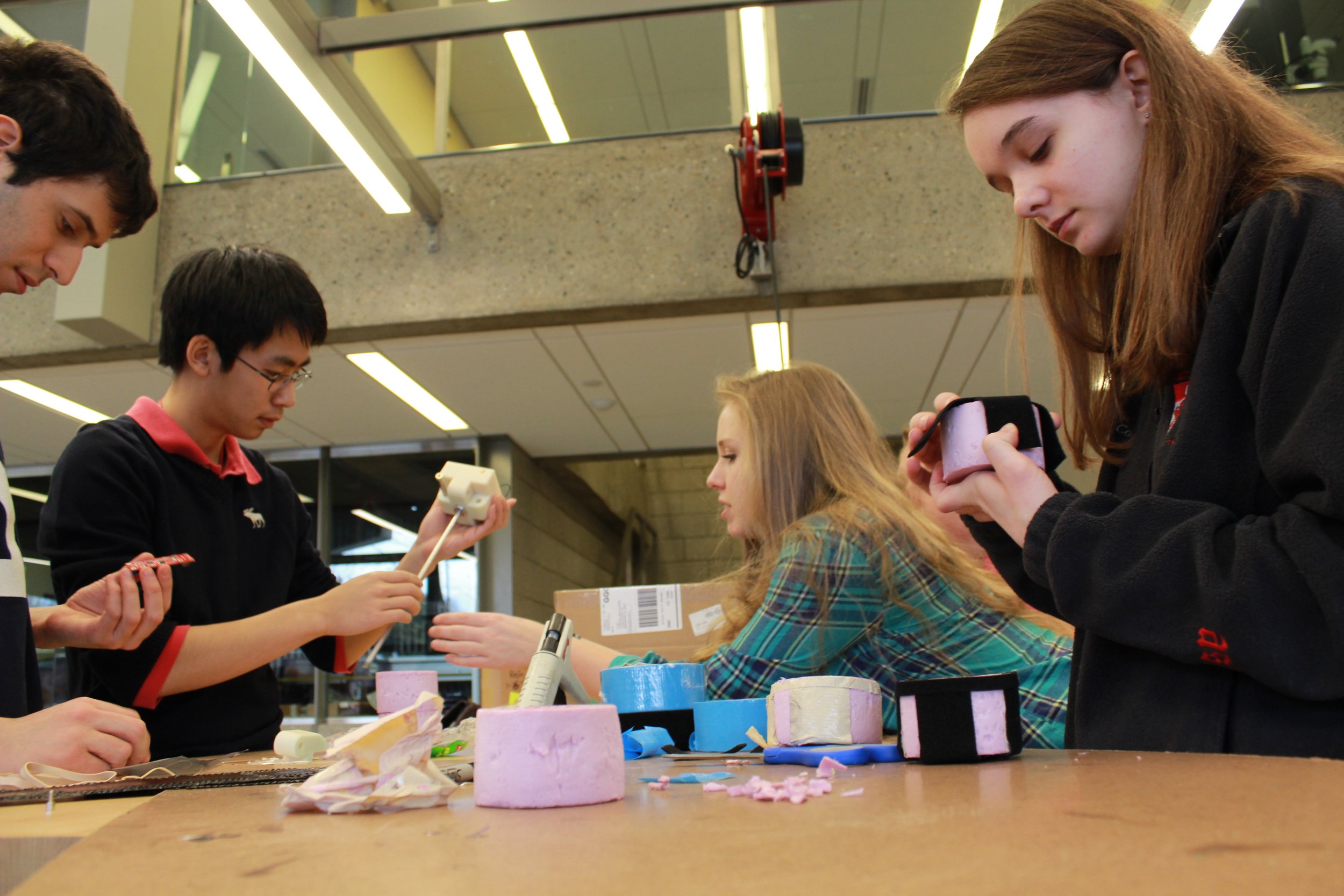
AEL team members building the EPS and Lander
EPS construction followed a multistep process. Carving the foam required constructing a cylindrical metal frame with a serrated bottom edge, and holes to hold a dowel handle. Using this circular “saw” made carving cylindrical sections out of 2.5-inch thick insulation foam easy. Each cylinder was then sanded until its surface was smooth.
Next, holes corresponding to an egg’s top and bottom were carved in pairs of foam pieces. To account for variations in egg size, the team built an EPS for each of six different eggs. A wooden square with an attached nut was epoxied into an indentation in each top section, and Velcro strips held everything tightly together.
Rocket
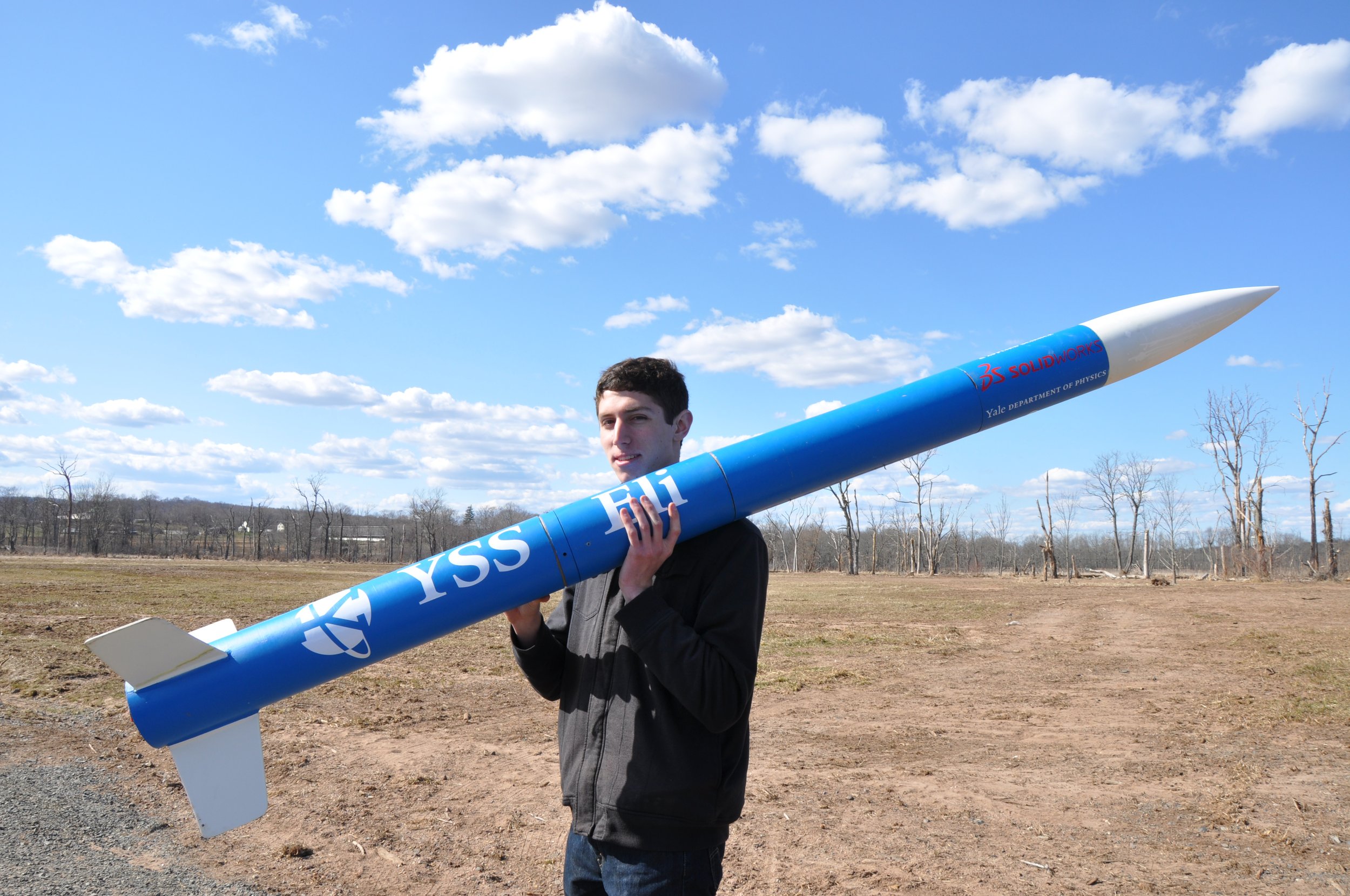
YSS Eli Whitney
The YSS Eli Whitney stood over seven feet tall and included space for a parachute, cargo compartment, electronics bay, and motor mount. Its design began by using RockSim simulations to determine a maximum practical diameter. The results led to the choice of 5.38 inch LOC Precision spiral paper tubing: a simple, strong, and cheap material. Standard trapezoidal fins made of 3/16 inch plywood permitted both efficient flight and easy construction.
The rocket’s 28-inch lander bay was split lengthwise and held together by tube sections at the fore and aft ends. When Pyrodex charges blew off these sections, the bay fell into two halves, releasing the lander. Each half contained a bulkhead to protect the payload from the blasts. Shock cords connected the halves to each other andthe rocket’s upper and lower sections, ensuring that the rocket was recovered in one piece. Because the wires from the electronics bay to the upper charge passed through the lander compartment, they had an attached Anderson Connector breakaway to allow separation.
To maximize power and reliability, the team chose to use a reloadable high-power composite motor. Once ignited, these composite motors continuously burned their solid propellant until combustion ended.
Rocket motors are rated on an alphabetic scale of increasing power from A to O. Any motor above G requires high power certification, such as that available from the National Association of Rocketry (NAR). Rocket motor performance is determined by the force of the expelled gas, called thrust, or the thrust times burn time, called total impulse. The higher the total impulse, the more powerful the motor.
The YSS Eli Whitney was designed with a 38mm motor mount able to hold a wide range of reloadable high-power motors. After conducting simulations with RockSim, the team considered both the Aerotech I-435T and the more powerful I-600R. The thrust curves below showed the motors burning for roughly 2 seconds each, with a peak thrust of 150 pounds for the I-435 and 250 pounds for the I-600. Both motors have total impulse between 600 and 650 N·s.
Testing
The AEL team launched the YSS Eli Whitney three times prior to the Battle of the Rockets, once on 16 March 16 2013 and twice on 30 March 2013.
First Launch of the YSS Eli Whitney
On March 16, YSS Eli Whitney‘s flight and safe recovery successfully marked YUAA’s first ever high power rocket launch. The I-600 motor ignited and the parachute deployed, but as the rocket drifted down from only 1,126 feet, the lander became tangled in the shock cord below the cargo bay, unable to spin. Not only did the unexpectedly heavy rocket fall short of 1,500 feet – the lander didn’t even get a chance to fly!
On March 30, the Whitney flew twice more. On the first launch, again on the I-600, the rocket reached 1,146 feet. This time, instead of getting stuck, the lander spun so fast that its rotor head sheared into five pieces. The team would have only a week to redesign and reprint the 3D-printed part.
The second launch used a more powerful motor, the J-350. With the lander out of action, a partially filled water bottle tied to a tiny parachute simulated its weight. Still, the rocket reached only 1,177 feet. In need of a motor with just a little more power, the team decided to upgrade to the J-410 for the competition.
Competition
April 6: Competition day finally arrived. Each team had up to three chances to win by launching its rocket the closest to 1,500 feet. On the YSS Eli Whitney‘s first launch, the force of lander deployment pulled apart the nose cone section, trapping the lander in place. While the shock cord kept the rocket parts attached, allowing a safe recovery from an altitude of 1,628 feet, the lander’s not deploying disqualified the launch.
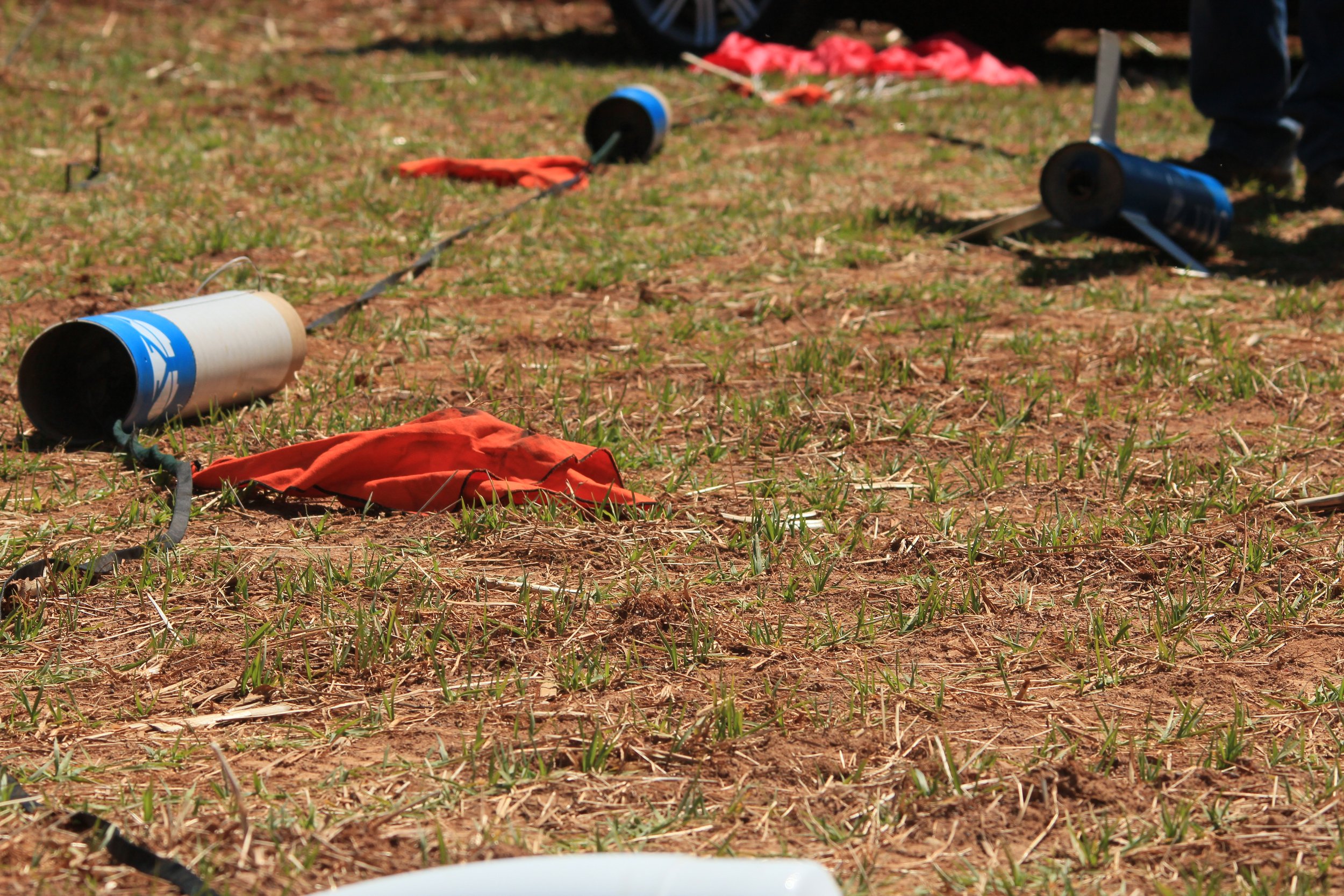
Recovery of the first launch. The cargo bay is closed, the lander undeployed.
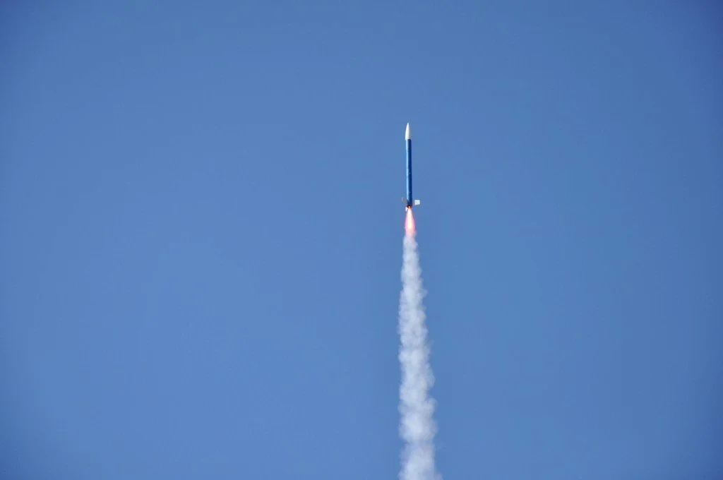
The team repaired the nose cone using zip-tie reinforcement and more effective epoxy placement, and prepared for a second launch. Another unsuccessful attempt would mean only one chance left, and time was running low. However, this time the Eli Whitney pulled through – the rocket soared upward, and, at its highest point, the cargo compartment opened. The lander had deployed.
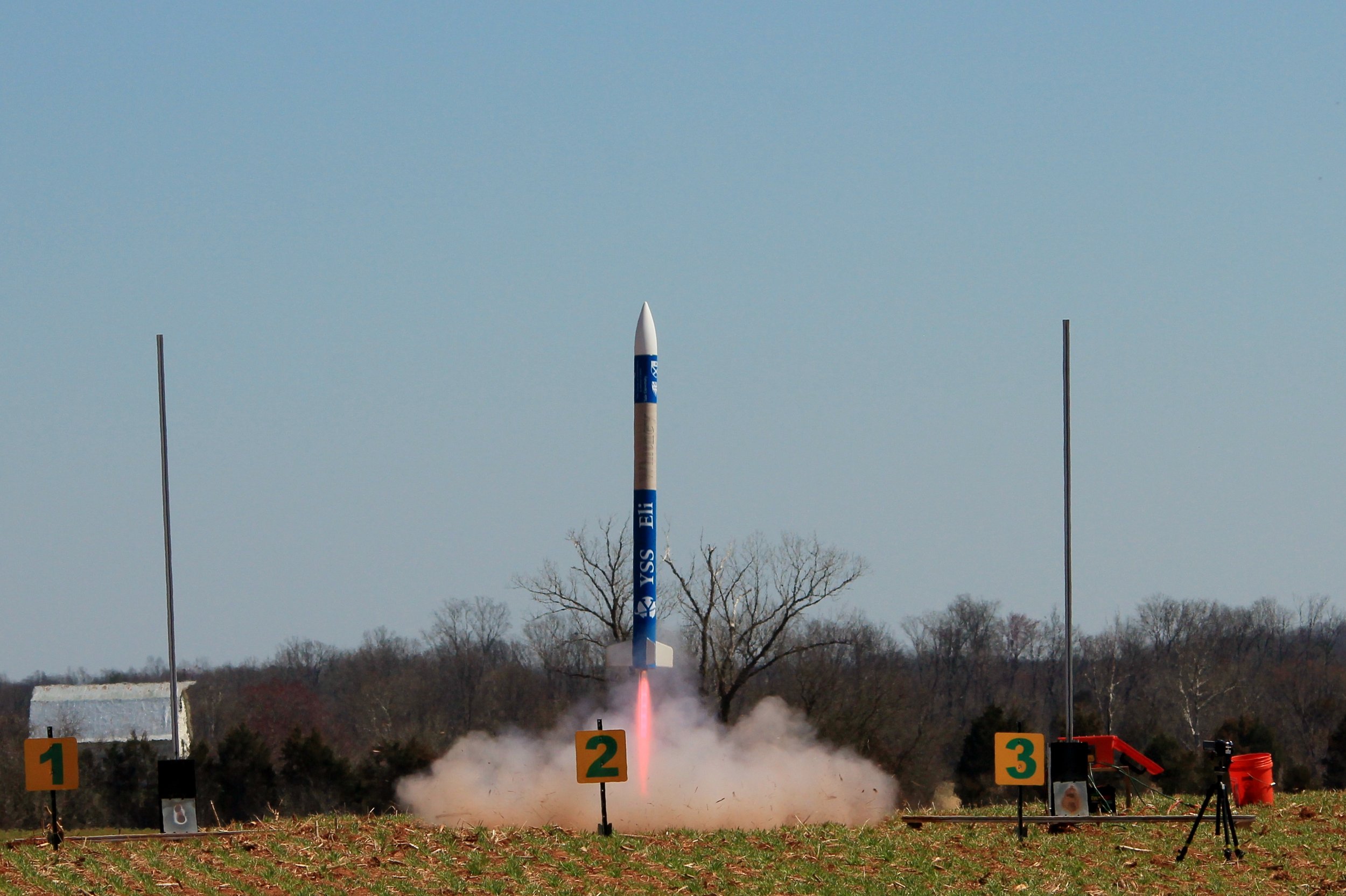
Launch of the YSS Eli Whitney
After the aircraft settled, the team spread out and searched the park for the rocket and lander. Thomas Ryan found the rocket, and listened as the altimeter beeped out its maximum altitude – 1,599 feet. Meanwhile, the lander had landed intact, and Kathy Gea gingerly carried it to the judges for inspection. Peeling the Velcro from the EPS, she revealed the egg – unscathed.
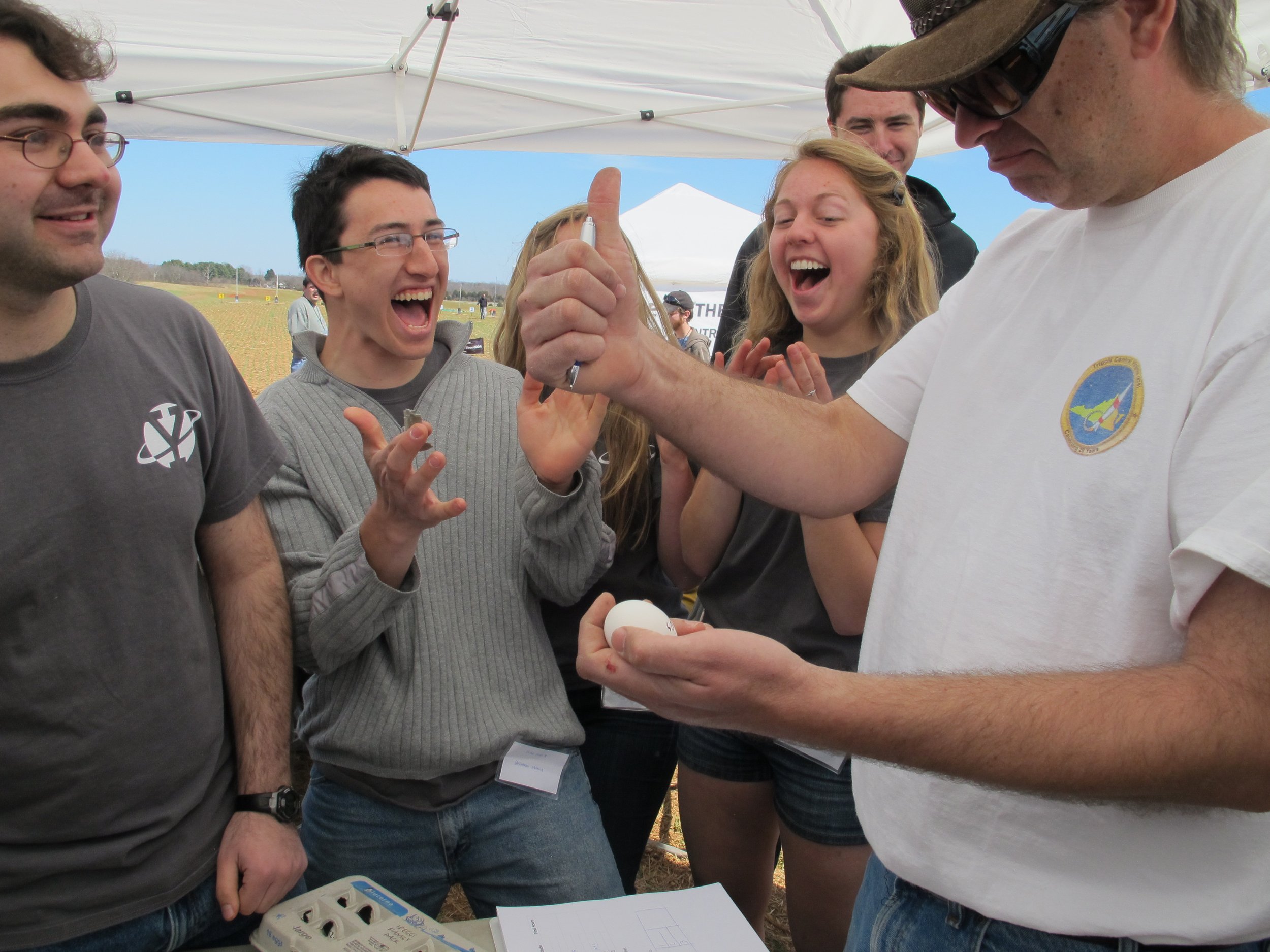
Success!
Not yet content, the team scrambled to prepare the Whitney for a third launch to try for an even better score. Ready just in time for the day’s last scheduled launch, the YSS Eli Whitney reached 1,571 feet, 28 feet closer to the target than the previous attempt, and the lander deployed and landed. Upon recovery, the team discovered that it had achieved its mission: the egg was undamaged once again.

In the end, no other team managed to both recover their egg and reach an altitude sufficiently close to the target. The YUAA Astro-Egg Lander Team won the competition.
Click here to learn more about the team’s victory.