
Multi-Stage Rocket
The multi-stage rocket project was focused on successfully launching and recovering a rocket with two or more stages. The team's main goal was to design the upper-stage fins, stage separation mechanisms, recovery systems, and other parts unique to a multi-stage rocket. To achieve this goal, the team used a mixture of commercially available and custom-made components to construct a rocket with the ability to reach an altitude of 10,000 feet.
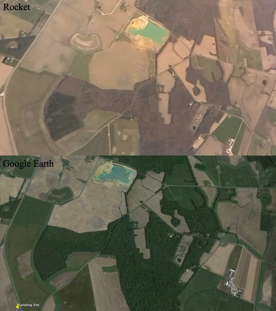
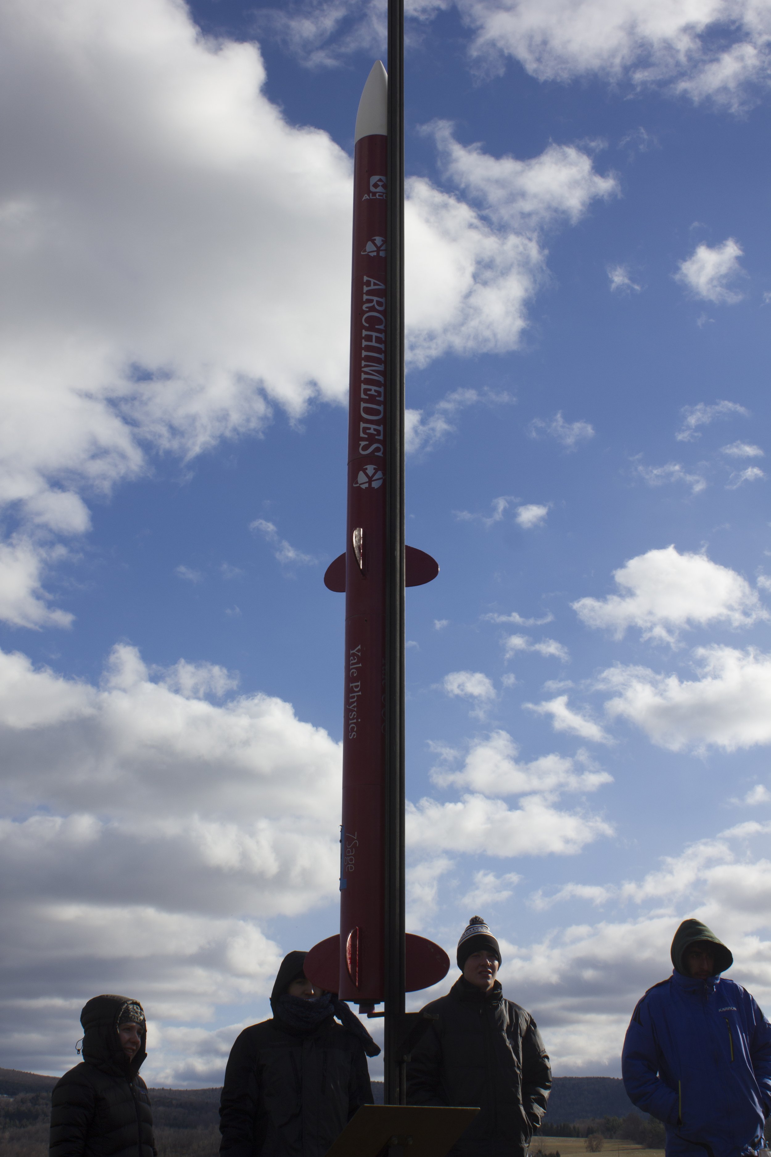
Along with the Rocket Competition team, the Multi-Stage Rocket team carried out a test launch in mid-November 2014 in the fields of Cobleskill, New York. For the test launch, the 9-foot tall red rocket “Archimedes” contained just one motor but still separated into stages after deployment, reaching a peak altitude of 2,400 feet. Eventually, Archimedes was supposed to contain two stages, fired one after the other in succession in order to reach higher altitudes.
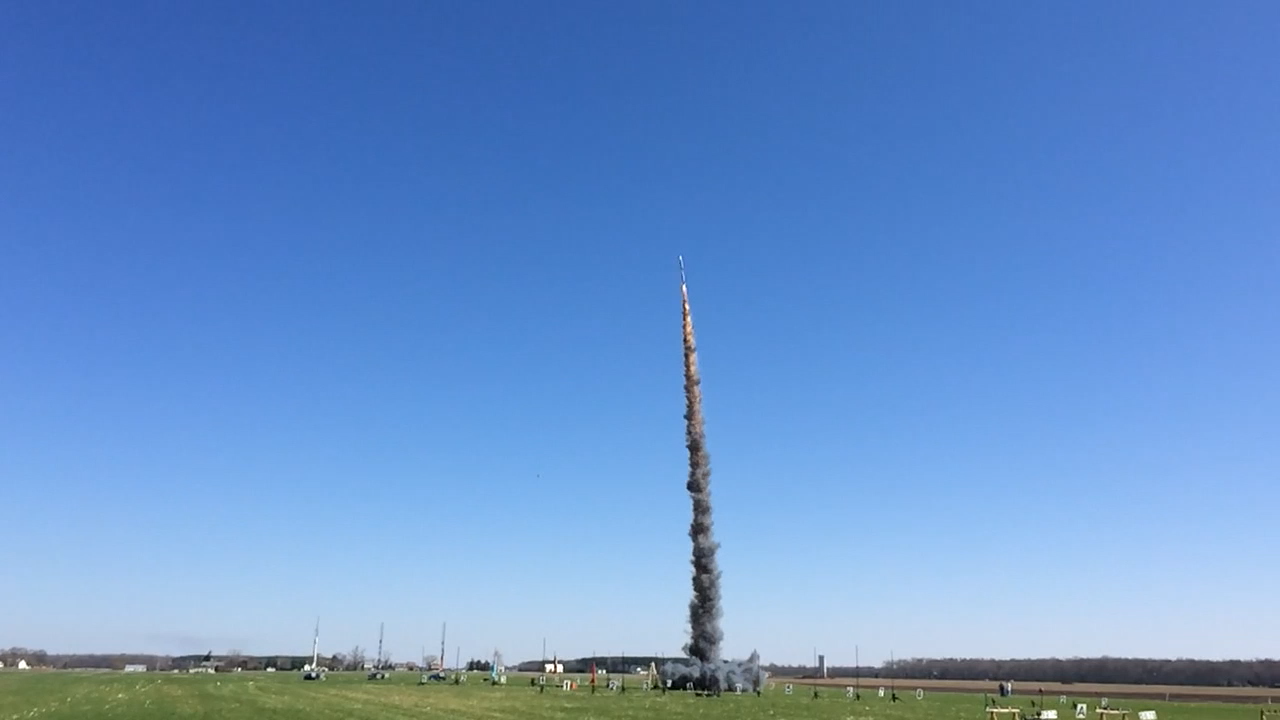
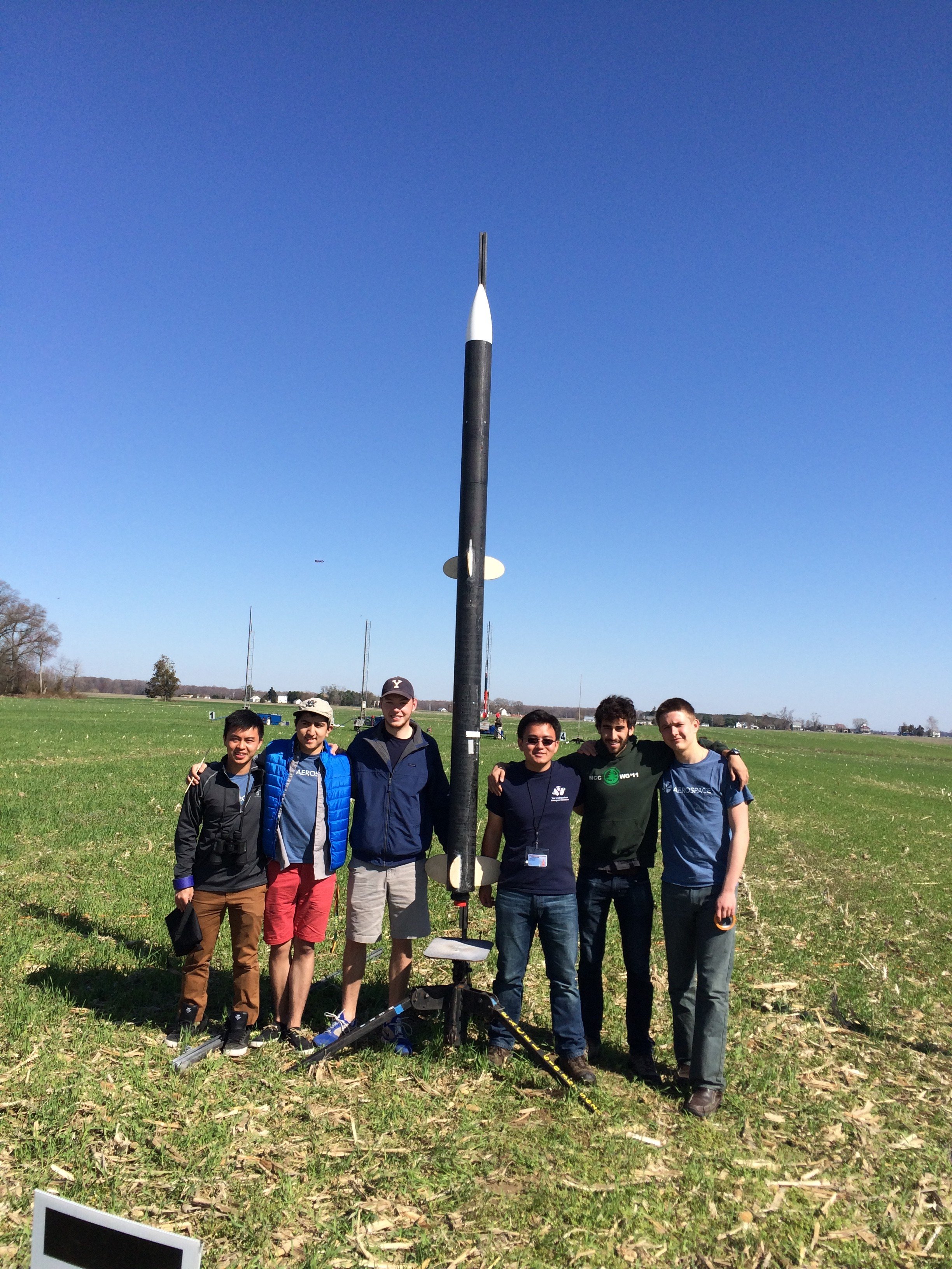
In the second phase of the year, the team would create Archi”meme”des, an ink-black two-stage rocket which successfully launched to 9617 feet, with a booster stage apogee of 3600 feet. This holds the YUAA altitude record for the highest confirmed rocket flight. However, an experimental drogue parachute failed to work.
One of the team's new attempts to deploy the drogue was to add a side door, constructed by cutting the body tube with a Dremel and attaching eye bolts to the bulkheads or centering rings. These were looped to the parachute and then connected to an eye bolt attached to the side door. The side door was attached to the body again by attaching thin metal sheets with epoxy and then using shear pins to hold the entire piece in the rocket. Unfortunately, the deployment of the side door was inconsistent.
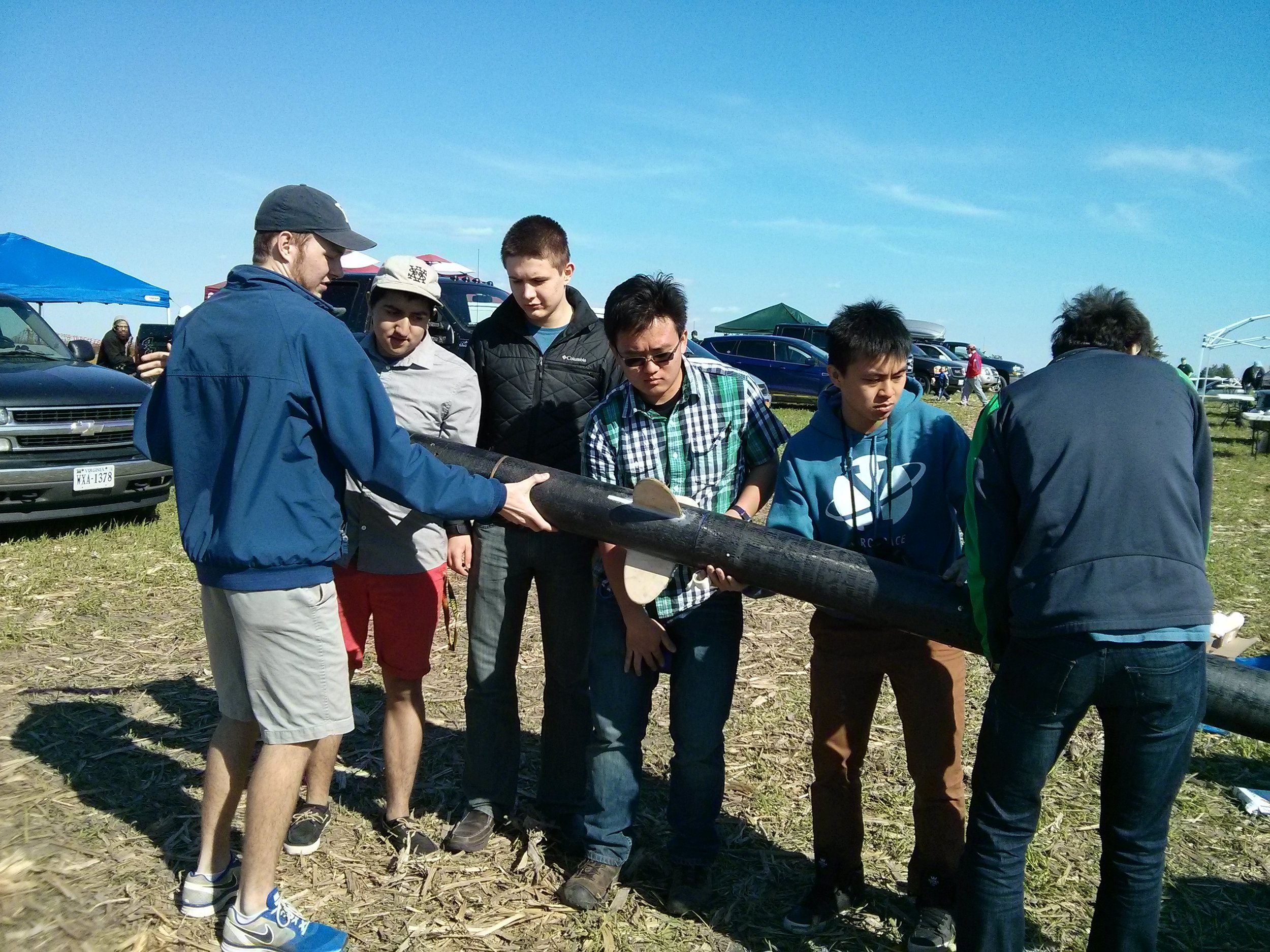
The team also tried to reduce the overall weight of the rocket to attain the highest possible altitude by using carbon fiber on the body tubes. They cut cardboard body tubes to length, then applied a carbon fiber layup using carbon fiber sheets and regular West Systems 105/206 epoxy. They decided on a thickness of 2 layers of carbon fiber and sanded the cardboard body tubes before the layup. The team believed that the thickness might be optimal. They cut a sheet of fiber at least 2X the circumference of the body tube in length (for two layers) and the width of the carbon fiber sheet should be longer than the length of the body tube by about 4 inches.
Before cutting the carbon fiber sheet, they taped along the cut path and cut in between tape edges to prevent fraying. The carbon fiber sheet was then laid on a flat, polyfilmed surface and rolled with the body tube to ensure there was enough material to form 2 layers of carbon fiber. After all surfaces of the carbon fiber were wet and permeated with epoxy, they placed the body tube along one edge of the carbon fiber, centered such that there were a few inches of extra carbon fiber on both sides of the cardboard body tube. The team then carefully rolled the body tube with the epoxy-saturated carbon fiber tightly with multiple people smoothing the surface and removing any air bubbles.
The body tube was tightly rolled with carbon fiber by wrapping it in a sheet of perforated polyfilm filled with small holes. This helped squeeze out any excess epoxy from the body tube. Maximum tightness was achieved by using a mesh-style roll of tape and wrapping it tightly over the perforated carbon fiber. The body tube was completely covered with the tape or wrapped at the two edges of the body tube and then at the center. The perforated polyfilm was wrapped as tight as possible, but using polyfilm with tiny holes created slight bumps wherever the epoxy oozed out, requiring sanding to smoothen them out. It became important to come up with a clearcoat/smoothing method for future projects.
To keep things clean, the body tube, carbon fiber, perforated polyfilm, and mesh tape rocket part were wrapped in one more layer of non-perforated polyfilm and left to dry. Afterward, the tape and polyfilm were removed, and the body tube was lightly sanded down to smoothen it.
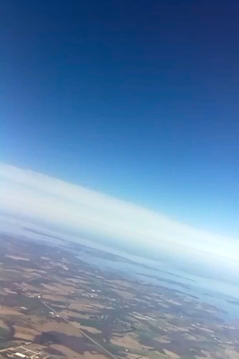
For the booster stage e-bay, an altimeter and two timers for ignition of the second stage motor were used. The second timer was for redundancy and ultimately not used. The top stage e-bay consisted of two Raspberry Pis powered by cellphone battery chargers capable of providing 5V/2.1A. These were connected to cameras and IMUs for flight characteristic data acquisition. Although the IMUs used were easy to interface with the Raspberry Pi, they did not provide any data for reasons unknown. A program was developed to start automatically upon powering the Raspberry Pis which waited for a button to be pressed to begin recording video and saving IMU data to .dat files. Pressing the button again would shut down the program, saving the .dat files and camera footage. However, upon retrieval of the electronics bay, pressing the button did not shut down the program.
Overall, the Raspberry Pis were inexpensive and capable, but they were finicky in practice and necessitated replacement with more robust electronics in the future. The idea of having interlocking "racks" to mount all components of the e-bay on was experimented with. Although total universality was not achieved, the constructed racks were space-efficient and easy to assemble inside the rocket.
We encountered some issues with the ABS plastic racks that we 3D printed for the Archimedes rocket. Unfortunately, they were not strong enough to handle the drogue deployment charge in an adjacent compartment. We determined that it would not be sufficient to just move the charge away from the e-bay as this would create other challenges in terms of rocket layout. Additionally, the shock of the charge could still potentially disrupt e-bay components.
Moving on to the second stage, we used a perfectflite minitimer 4 to trigger ignition using an accelerometer. We initially considered using lipo batteries and a standard 12V/3A igniter, but we were advised against it due to reliability issues with high-current igniters. Instead, we opted for an e-match, which cannot ignite a high-power motor but can ignite Blue Thunder propellant, which burns at a high temperature.
To create the impromptu igniter, we glued a piece of low-power Blue Thunder motor onto the end of a dowel, along with the e-match head nestled in a pre-existing cleft in the motor. Triggering this successfully ignited the motor we used for the second stage. It was essential that the whole dowel fit smoothly into the nozzle for a safe ignition as a blocked nozzle could potentially cause the engine to explode.