
Radio Astronomy
The Radio Astronomy team created a fully steerable radio satellite dish complete with a collection of signal processing hardware and software. Along the way, project members were taught the basics of astronomy, signal processing, and data processing. To bring this knowledge and understanding to the largest number of people possible, we held demonstrations of the dish functionality at high schools in and around the New Haven area. The project, along with CubeSat, was the only collegiate team to be mentioned at the 2015 White House Astronomy Night.
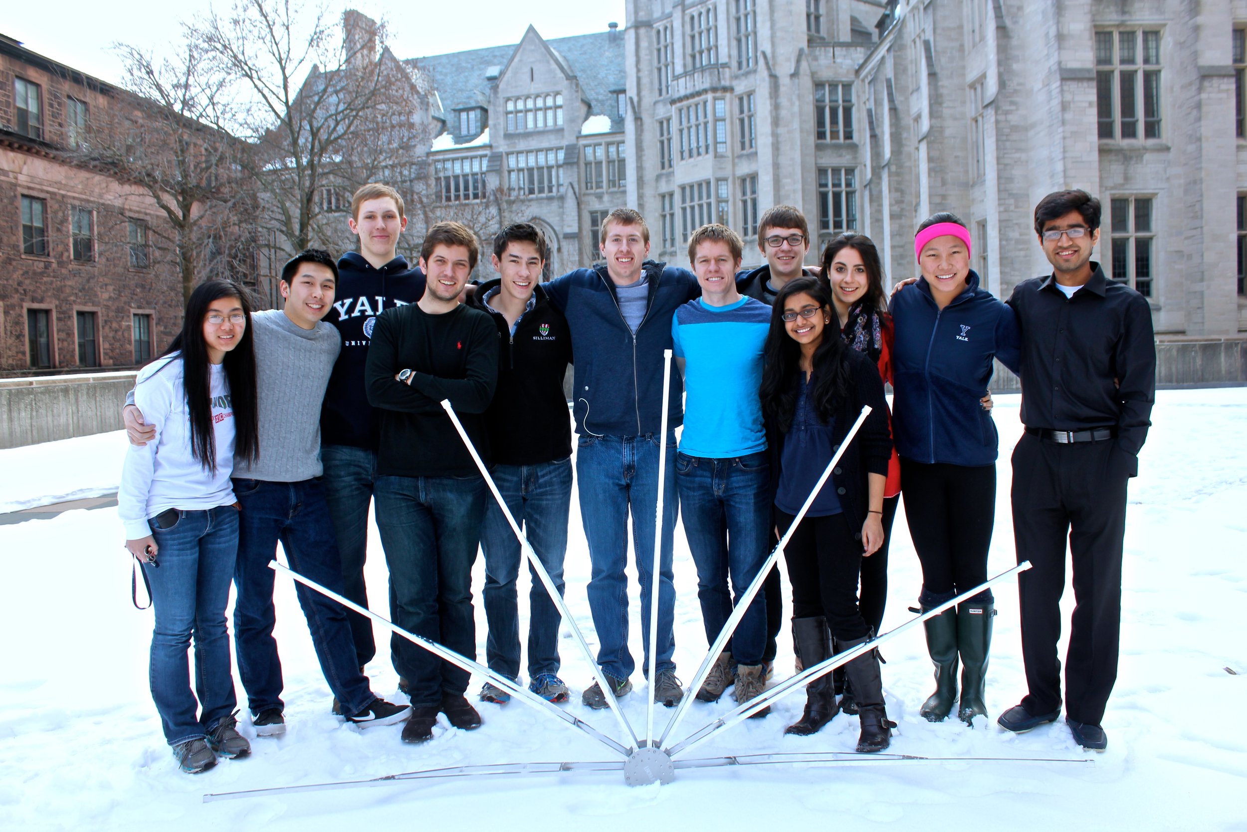
While many radio telescopes of this variety are built as kits modeled off the MIT Small Radio Telescope, our dish was built from scratch. In particular, almost all of our component parts - mount, receiver, code to control the telescope and collect the data - were student-designed and produced. While this presented a number of practical challenges, the practice ensured that all members understood every element of the instrument and nothing was left as an untouchable “black box.” The project was completed by a team of fourteen students with a wide range of technical backgrounds and shared interests in learning about how astronomy’s primary tools (telescopes, and interferometers) are constructed.
Prototype Dish (First Semester)
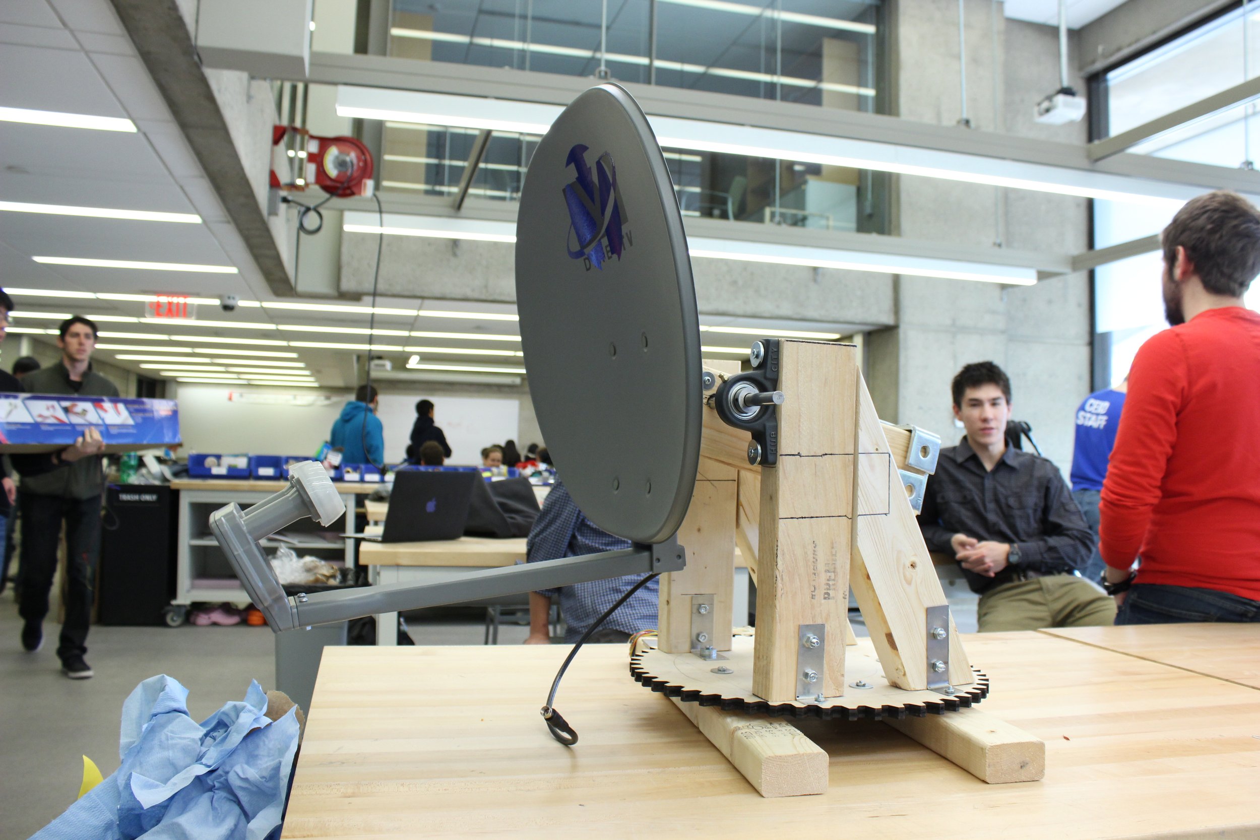
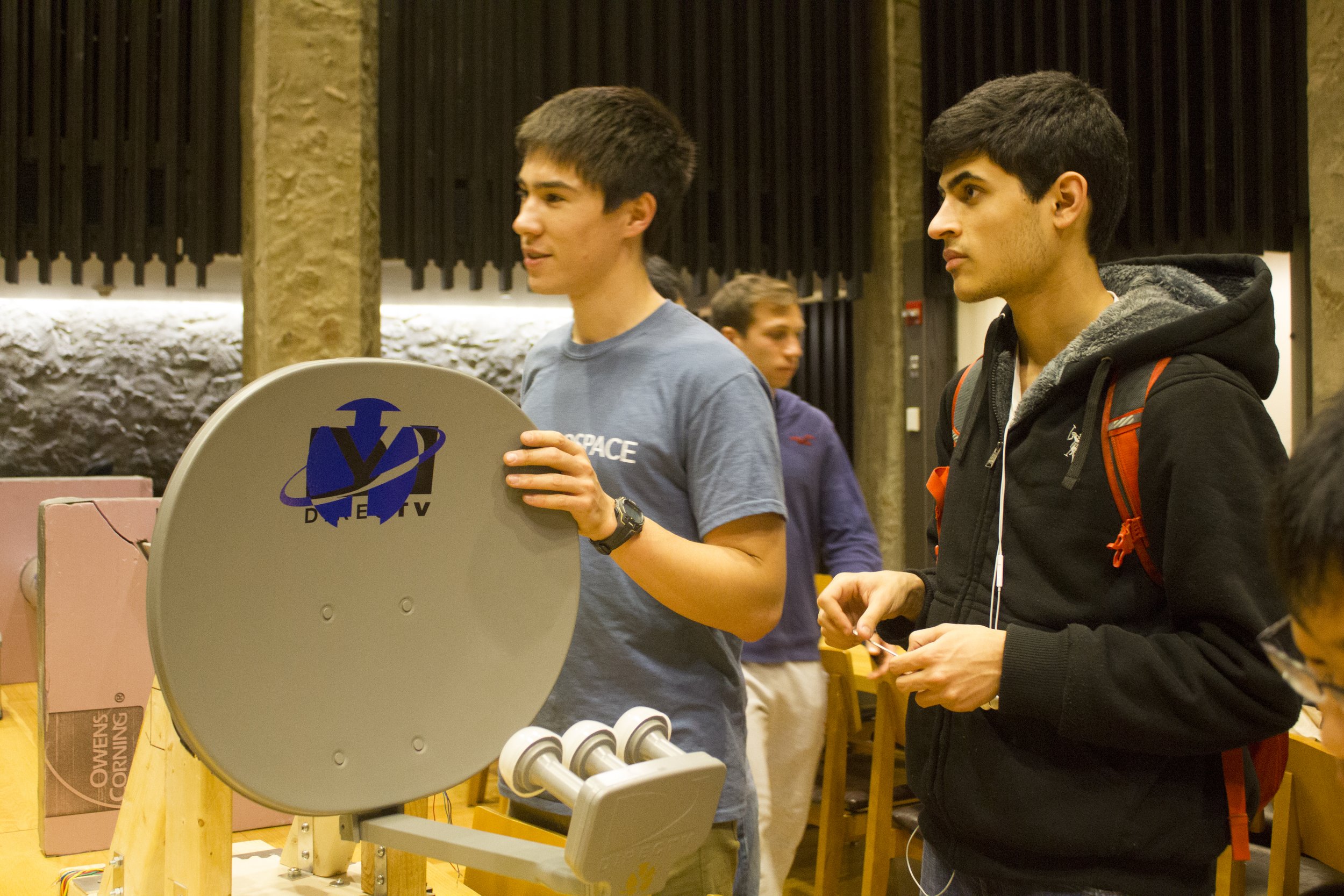
The project began in early August with approximately 18 members. Realizing that the majority of the project members were eager to get involved in hands-on work, we made the decision to focus in the short term on a prototype radio telescope made out of an 18-inch satellite TV dish.
By the second meeting, we purchased a dish and began drawing up plans for its motorization, building signal processing apparatuses and a support structure. We decided to mount the dish on a lazy-susan-like base so the dish could rotate azimuthally. To control movement in the elevation axis, we welded a rod to the back of the dish, employed ball bearings, and used a stepper motor to complete the actual movements. Because the dish was so heavy, we used a counterweight to balance it and a 64:1 gear ratio to facilitate the movement. Nevertheless, the motor struggled to move the dish. The azimuthal rotation faced its own unique set of challenges. The team used a laser cutter to create a set of gears out of plywood. The dish would sit on the large 50-tooth gear while a smaller gear attached directly to the stepper motor.
The electronics team spent the first semester looking at different options for data collection and power. In order to control the rotation of the prototype, the team decided to use two bipolar stepper motors that would control the lazy-susan and the angle of the satellite dish. In conjunction with the stepper motors, the SparkFun Easy Driver was used to control the power distribution to each of the motors. The electronics team worked on wiring the stepper motors and drivers and coded the motors for movement. The other area that the electronics team worked on was figuring out how to create bridge rectifier circuits in order to read DC voltages from the alternating current signal.
By the end of the first semester, we purchased all the parts that we thought we were going to need. However, due to the asymmetric design of the azimuthal base, much of the weight was positioned over the edge of the gear. Combined with a low-quality lazy-susan ball bearing structure, our little stepper motor was unable to consistently rotate the dish. By the start of the second semester, the decision was made to abandon the prototype in favor of the main dish, which had been purchased over winter break.
The Big One (Second Semester)
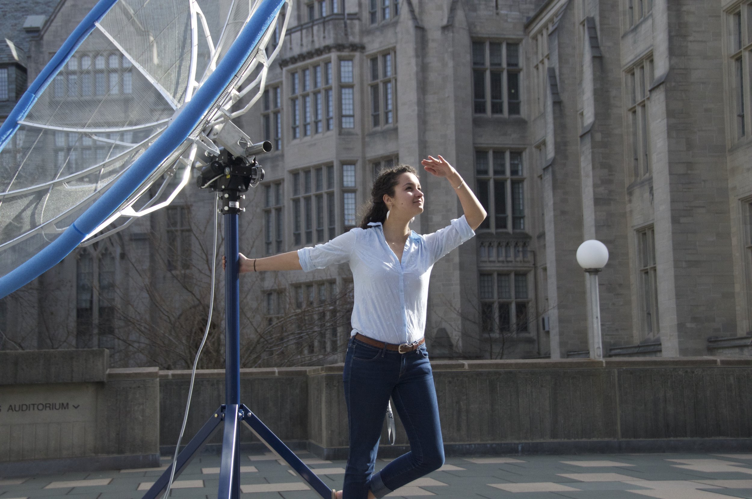
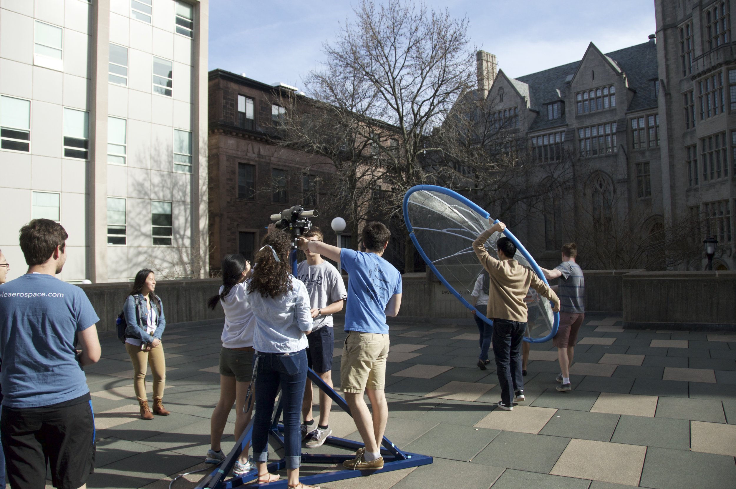
While conducting research on small radio telescopes, we came across designs for the MIT Haystack Small Radio Telescope (SRT). These designs had a large impact on the direction we took the project. From their documentation, we learned of RF Ham Design, the company that then became our main supplier for the 2.4-meter dish, the AZ/EL rotator, and a variety of accessory components.
At the start of the second semester, the team was divided into 3 sub-teams, each with its own leader. Each of these teams was in charge of certain things: Mechanical Design, Robotics (controlling the dish), and Electronics (Signal Processing).
Mechanical Design
Design
We decided to go with a triangular-pyramidal tripod-like design using 2-inch square tubing. The middle of the tripod featured a 2.6-inch steel mast which bore the brunt of the weight of the dish. This mast wasthen supported by 3 legs (square tubing) attached via a "collar". The collar transferred all the horizontal forces (wind, rotating, imbalances in the dish due to torquing asymmetries) to the legs, where they are balanced out.
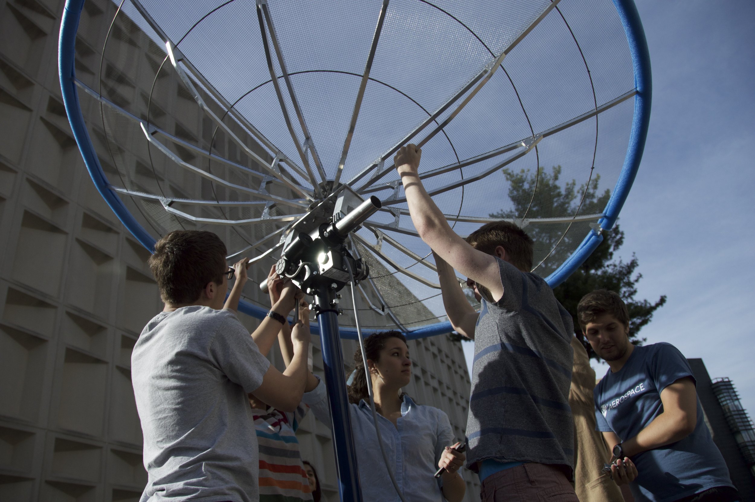
The dish was built as per the directions provided with the kit. 12 aluminum arms were attached with bolts to a central hub. Lastly, a mesh was stretched over the arms and riveted in place.
Signal Processing
Design
For the antenna, we followed a design found in the SRT documentation for a 1420 MHz circularly polarized antenna. This method consisted of a 7 inch cake pan to act as a type of feed horn and a length of adhesive copper ribbon wrapped around a foam core as an antenna. From this antenna, we attached an SMA cable to carry the signal to our Noelec SDR. The SDR and signal processing was controlled by the laptop. The SDR was controlled with a few commands in python.