
Optical Telescope
The Optical Telescope was built by 12 members from scratch with little to no engineering experience. A prototype mirror of 3.5” and a final telescope mirror of 12” were created. Both telescopes were worked on by the team over the year. The successfully built prototype was presented to K-12 students in New Haven outreach.
Progress
We intended to build this telescope from scratch, except for the mirrors, which we outsourced to a respected mirror manufacturing company. All other components were designed and built by our team during the year. We did this so that our members would understand all the components of a telescope at a deeper level.
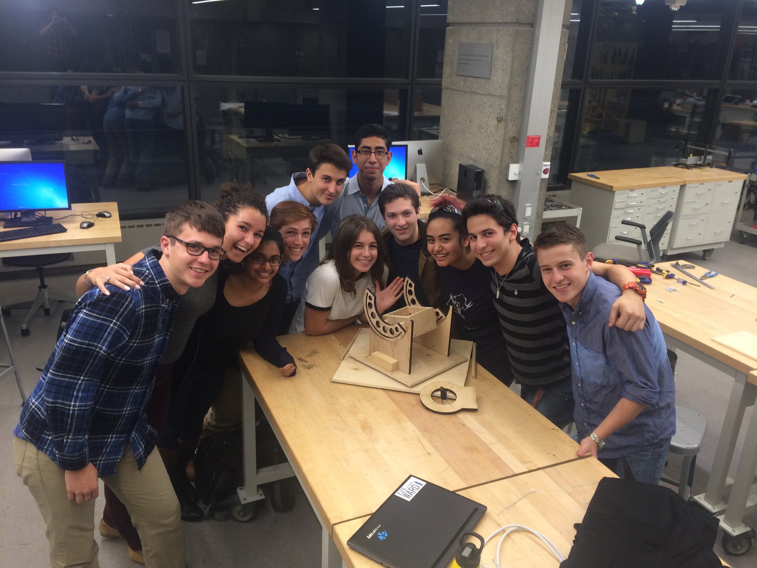
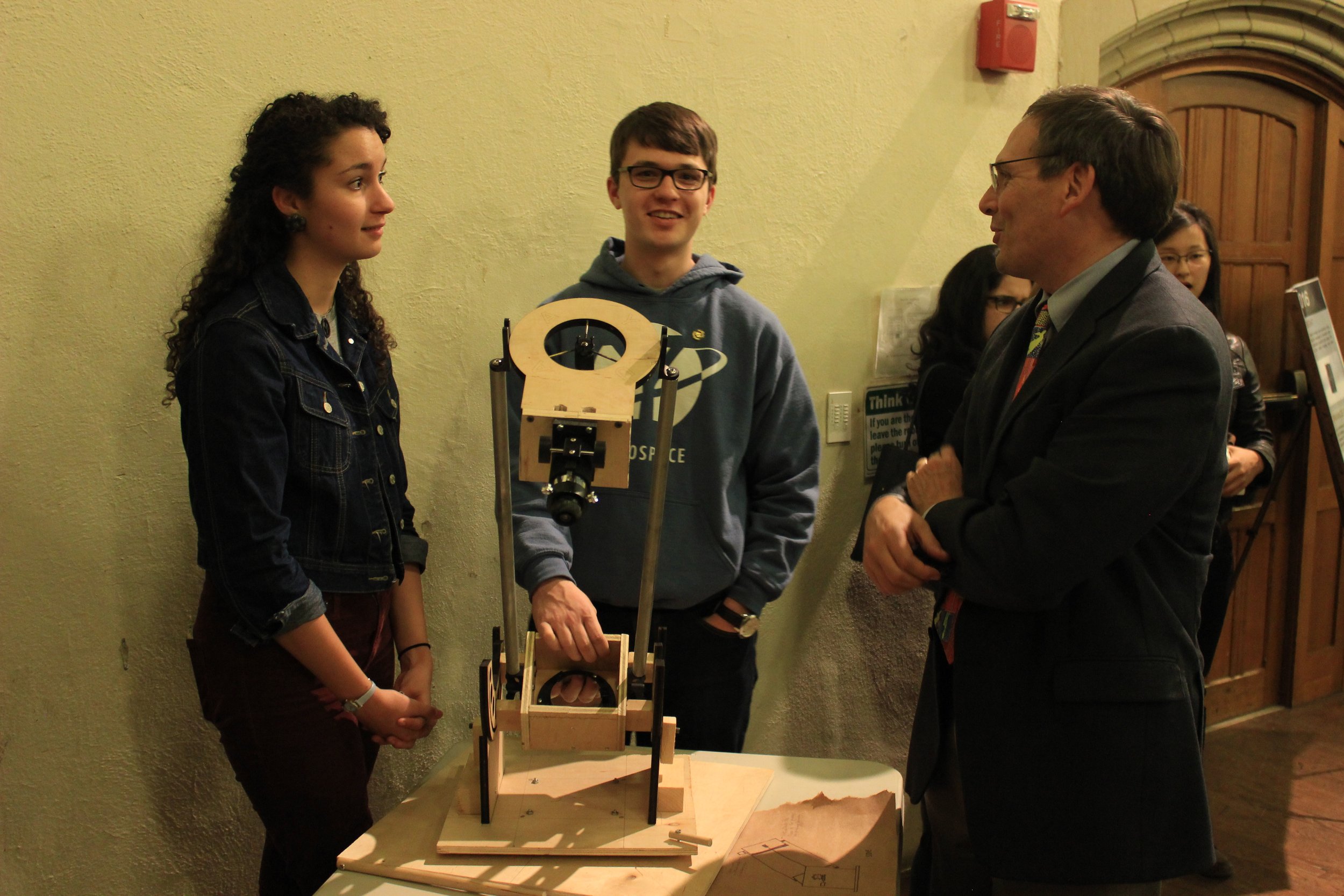
The project was undertaken by twelve students from diverse backgrounds, most with little to no engineering experience. However, they all shared a deep interest in astronomy and astrophotography. We began work with a prototype telescope which was much smaller than our final one. This prototype had a 3.5” mirror, while the final telescope’s mirror was 12”. This prototype presented many of the same challenges that building the full-sized telescope brought but on a smaller scale.
Planning
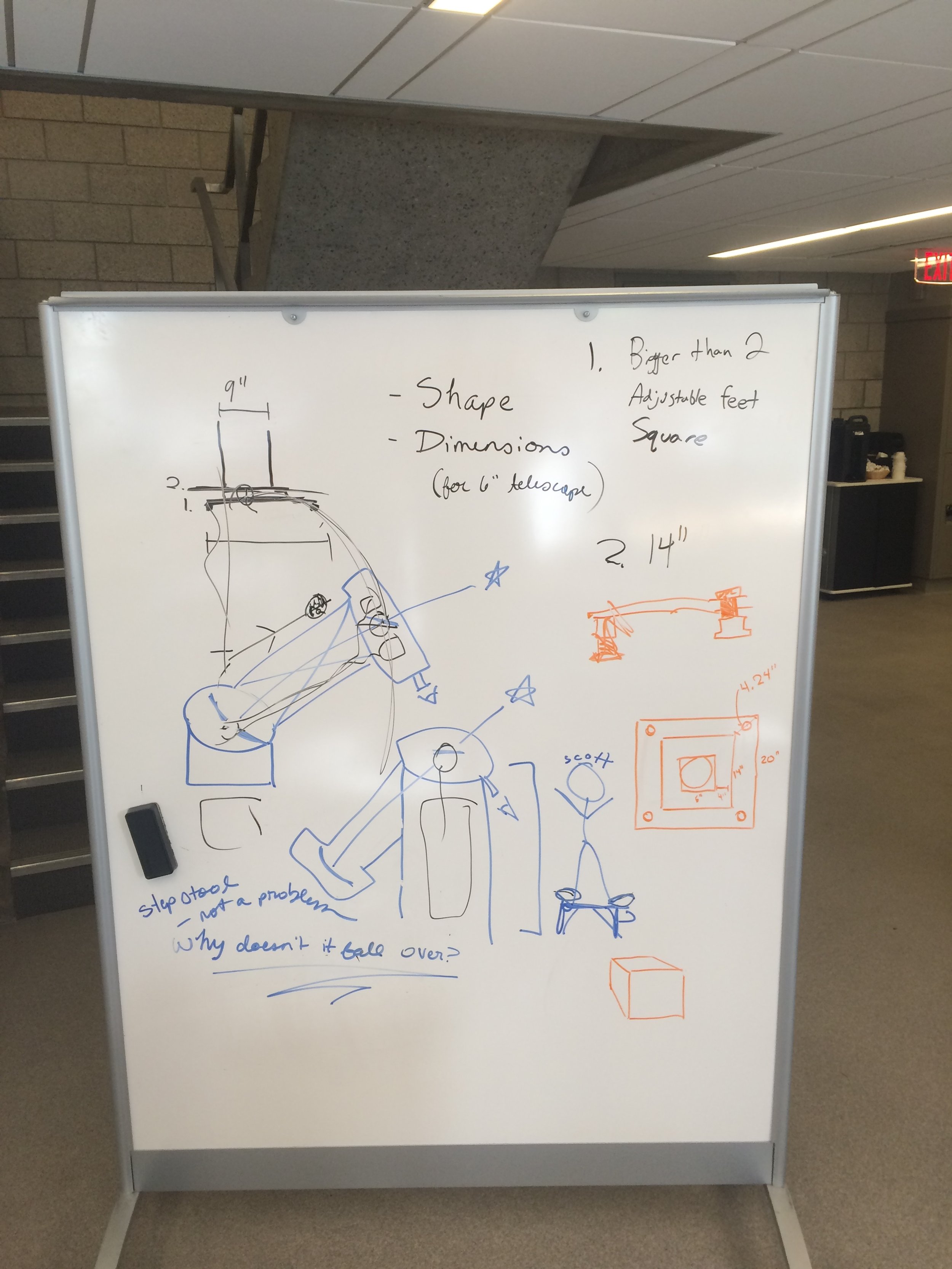
The project began with a high-level planning process. We discussed different telescope designs, and which would provide us with the best ability to take long-exposure photos. In terms of the mirror arrangement, a Newtonian design was the clear choice. It was easy to design, adjust, and only required two simple mirrors. We considered a Cassegrain design for a while because it allowed for better placement of observational instruments, but there were several problems with that design. One, it required a primary mirror with a hole in the center, which dramatically increased the cost. Two, the telescope would need to be elevated a large amount in order to allow for comfortable manual observation. If it was elevated, it would be more difficult to design a base that could support the size of telescope that we wanted.
The other design choice that we needed to decide on was the base. Once again there were two competing ideas. Initially, an equatorial base was the clear choice because it is the main design for any telescope meant to do astrophotography. An equatorial mount is one in which the base has an axis of rotation that can be moved to point directly at the north star. Since the night sky appears to rotate around this point, having the telescope rotate around this axis would allow for very easy tracking of objects in the sky. Once the telescope was pointed at an object, it would just need to be rotated around this axis at a steady rate and the object would remain in the field of view. However, there were several issues with this design. First, it was a fairly complicated base to design and make robust. Secondly, the scope must be elevated and there must be a counterweight to offset the weight of the scope. It would have been very difficult to make a stable base for the size of telescope that we wanted.
The other base design was a dobsonian base. A dobsonian base is very simple with only two axes of rotation: elevation (up and down) and azimuthal (side to side). It is easy to make robust to hold a large scope which fits with our needs. Its main drawback is with astrophotography. Dobsonian mounts do not allow for easy tracking of objects in the sky. Even if you are able to rotate around both axes of rotation to keep the object in your field of view, the object will rotate inside your eyepiece (or camera). This would make it very difficult to take long exposure photographs, which are essential to astrophotography. Fortunately, we were able to find a compromise to take the best aspects from both designs.
In the end, we decided to use a hybrid design, mixing an equatorial and a dobsonian. By simply adding a wedge to the bottom of a dobsonian mount, we could make the azimuthal axis of rotation be in line with the north star. This essentially gave us an equatorial mount without the complications that a normal one would bring. This would provide us with the stability required to build a large telescope and the ability to counteract the earth’s rotation while taking photographs.
Prototype
The team then designed and built a small prototype, with a small 3.5” primary mirror. We used many the tools in the Center for Engineering Innovation and Design, Yale’s engineering workshop. Team members were especially excited to learn how to operate the laser cutter which proved to be a valuable skill for the main telescope. Another design choice made was the choice to use trusses instead of a traditional tube. We wanted to use trusses, but were unsure whether or not they would be easy enough to design and implement. The main reasons for using trusses were decreased weight, easier access to the mirrors and other components, and, lastly, aesthetics.
Our first large shipping delay occurred at this stage. We ordered truss brackets vital to the construction of the prototype which set our project back a few weeks at the end of the first semester. Fortunately, the parts arrived when we returned to school for the second semester, and we were able to complete it within a week.
The prototype worked as a proof-of-concept that our hybrid design could work. The trusses worked very well and it appeared to be easy to make them fit for our final telescope. The construction went smoothly with all members working together on the different components. However, the mirrors were so small that very little of interest could be observed. We learned a great deal about issues that we could encounter with the main telescope, helping save time and money during the second semester.
Primary Telescope
Mechanical
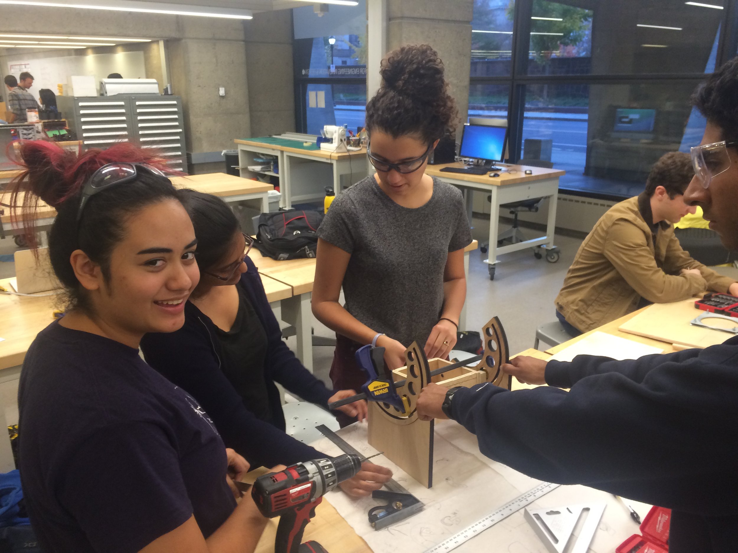
The mechanical subteam designed the overall structure of the telescope. After the team as a whole settled on the hybrid design, the mechanical team began designing and constructing the base and mirror housings. The base needed to be able to hold a large and heavy mirror and move freely on two axes. The base and housings were cut out with the laser cutter to provide the precision needed for the optical system. One of the largest changes to the design was using an axle system to allow for elevational rotation. In the prototype, we used two concentric circles which rotated on top of each other, but this design was not able to be easily motorized. By using an axle system, we were able to simply attach a gear to the end of one axle and connect it with a stepper motor to allow for the telescope to be pointed automatically. Ball bearings were used to allow the telescope to rotate freely when turned by the motors.
Our biggest shipping delay occurred with the mirror. We ordered a 12” high-quality mirror before winter break, but the shipping was delayed multiple times. We did not receive it until April, the last month that we were able to work on the project.
The cell that held the mirror was incredibly important to the design of our housing. It allowed for precise adjustment of the primary mirror which was necessary for optical alignment of the whole system. It also included a small fan to increase air circulation around the mirror. The slight warping caused by a difference in temperature with the outside air could cause pictures to come out blurry. The fan kept the mirror at equilibrium with the outside air and allowed for much clearer pictures.
Electrical
The goal of the electronics subteam was to motorize the telescope by designing a drive assembly in which stepper motors were driven by worms and worm gears. We had to do several calculations to determine the moment of inertia that the motors would need to provide. We were able to calculate the amount and found motors which would meet the requirements. We learned how to wire a BigEZ driver with an Arduino in order to control the microsteps of the stepper motors. The Arduino acted as a middleman between the computer program, controlling the whole process and the motors which could only take simple instructions. For this reason, the electronics team worked closely with the computer science group.
The motors provided the team with many difficulties. We eventually acquired help of an electrical engineering professor (incidentally, the same professor who found the mirrors for our prototype) to help us solve the problem.
Once the motors had been set up, the electronics team began working on building a gear system to transfer power to the actual rotation of the telescope. In our previous calculations we determined that a 50:1 gear ratio would be enough to move the telescope. We achieved this ratio by using a worm gear on the motor (which technically has one tooth) and a 50-tooth gear on the axles.
Computer Science
The computer science team designed the software that interfaced the computer with the motorization hardware, and connected planetarium software with the motor to track celestial objects. The software consisted of three main parts: the high low level commands which run on the Arduino and directly tell the motors how much to move.; functions in Python which converted high-level instructions to Arduino-understandable instructions and sent those instructions to the Arduino; high level guiding software which used astronomical information to track objects as the cross the night sky. An exciting development was the integration of planetarium software with the code. The team was able to use that software to click on an interesting object which then output the location of that object to the guiding software to move the telescope to that location in the sky. This made it very easy to look at many objects in one night.
Outreach at Conte West Hills Grade School
On May 2nd, three members of the team went to Conte West Hills Magnet School in New Haven to teach students about our project and several topics in astronomy. We visited Ms. Vanessa Clayton’s 7th-grade class and spoke to approximately 15 students. The students were very interested in our prototype telescope as it looked much different than any telescope they had seen before. We also discussed the different types of telescopes and how each type fulfills a different purpose in investigating the electromagnetic spectrum. To cap off our presentation, we had an interactive demonstration where students were given small diffraction gratings and looked at several different light sources to see the different emission patterns. We were impressed with how well the students were able to connect the demonstration to the other topics in astronomy that we mentioned, and the extent of their questions.