
Tiltrotor
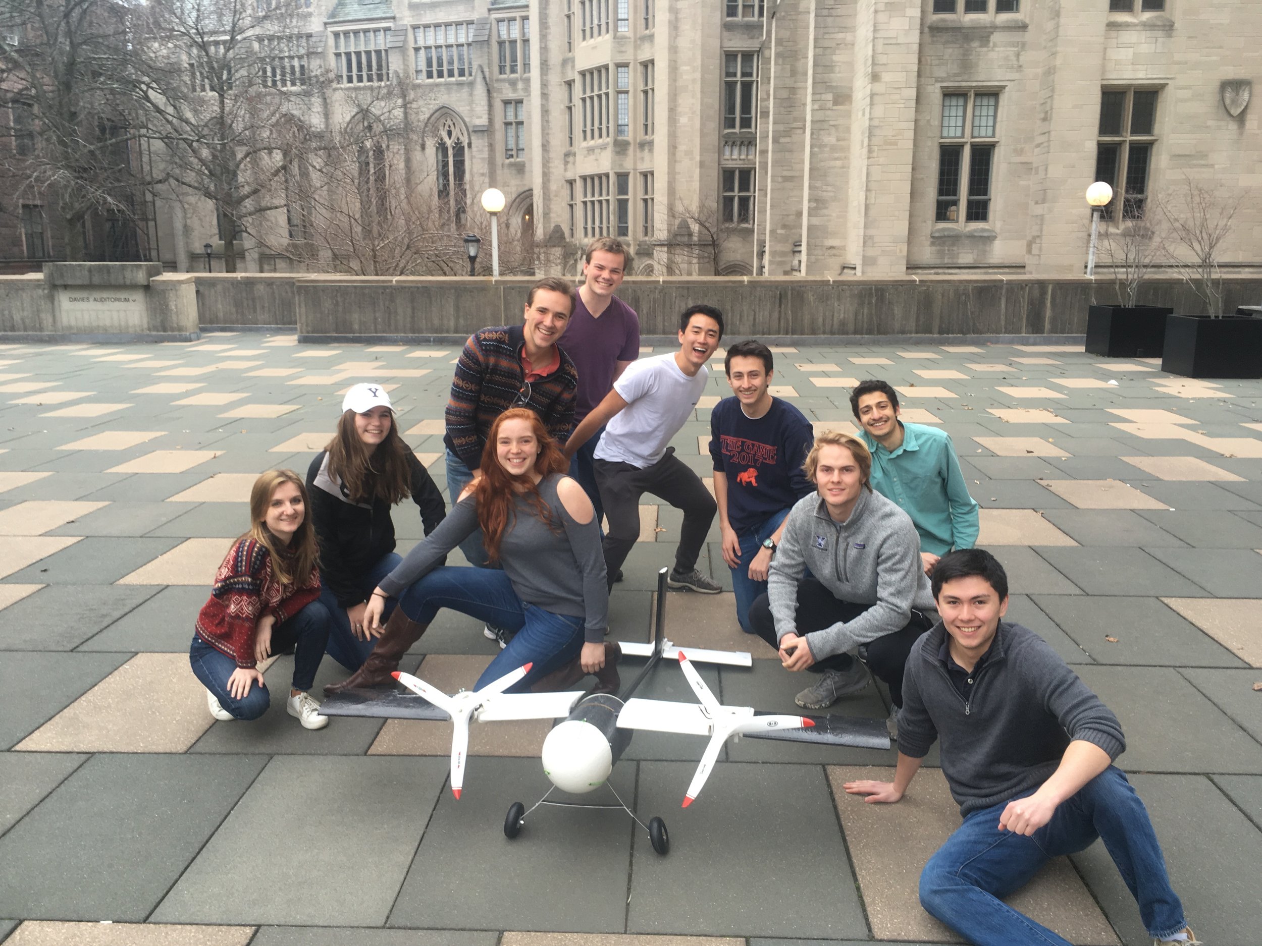
The primary goal of this project was to design and fabricate an unmanned tiltrotor aircraft capable of taking off, landing vertically, and flying using its wings for lift. The aircraft was completely designed and built by undergraduates and advanced YUAA’s knowledge and experience with RC airplanes and rotorcraft. At the conclusion of the year, the tiltrotor was ready for vertical flight testing and had demonstrated that the aircraft could output significantly greater thrust than its own weight.
Design Details
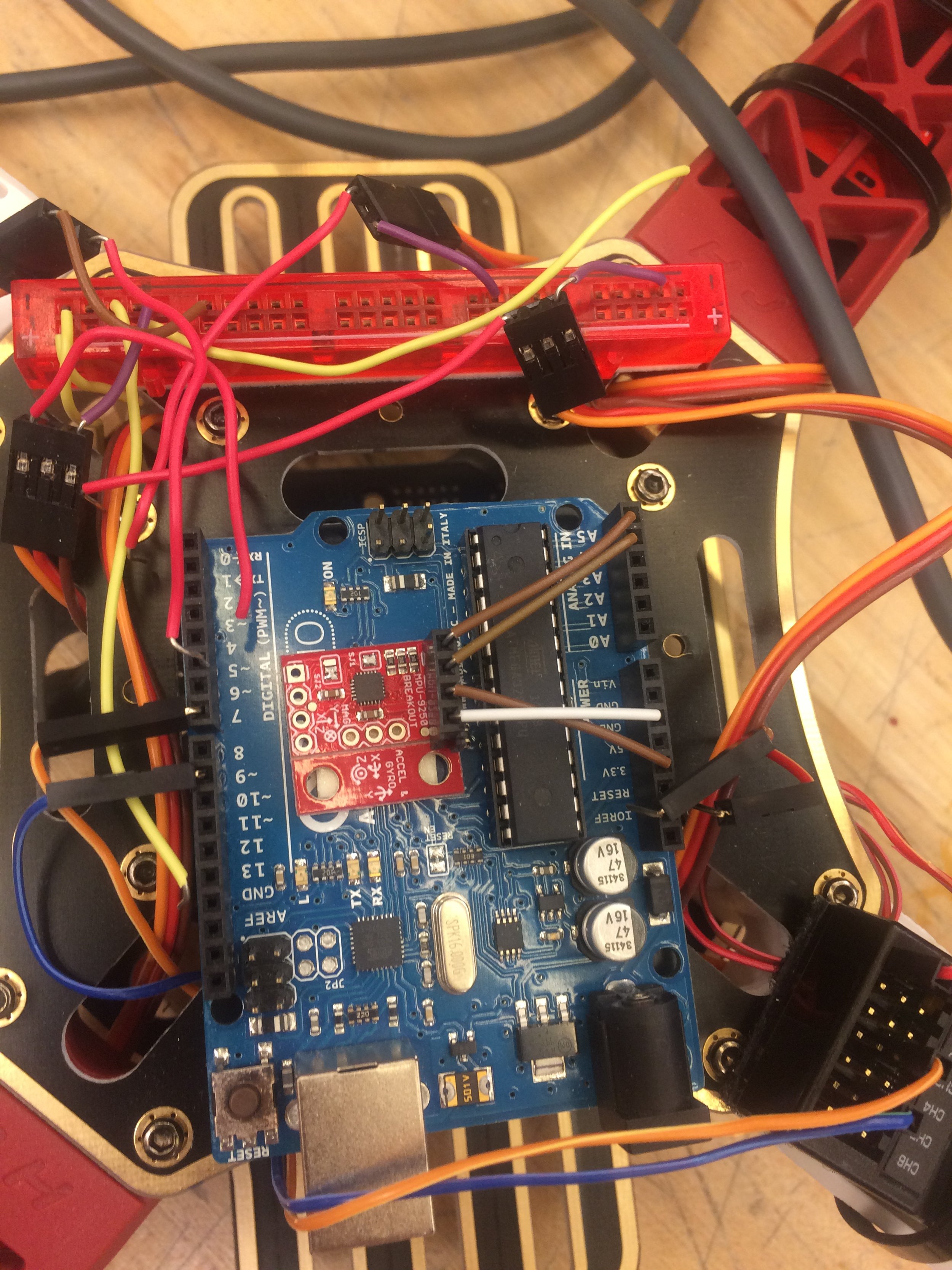
At the beginning of the year, the basic configuration of the aircraft was decided on. The aircraft was to use a shortened rocket body tube as its fuselage with a carbon fiber layup for additional rigidity and strength. All control electronics and batteries would be placed inside the fuselage. The vehicle would be powered by two primary motors on the wings which would spin three-bladed propellers. These motors would be actuated by servos in the wing and powered by LiPo batteries. Three blades were chosen to allow a greater thrust to propeller diameter ratio. The wing area was decided by aiming for a glide ratio comparable to a heavy glider or light powered aircraft. The tail would be a carbon fiber rod with a conventional stabilizer configuration. Two additional motors and propellers would be placed on the tail to allow for pitch control in vertical flight mode. The basic design was modeled in SolidWorks, and detailed parts were left to be designed immediately prior to fabrication. Once the basic configuration was completed, an estimate was made of the final weight of the airframe excluding all electronics (batteries, motors, wiring, etc.) so that the motor and battery sizes could be determined and a target payload could be identified. The team decided on a motor combo outputting up to ~6 kW of power powered by four 8.2 Ah 4S batteries. These batteries were to be connected in series to create two 8.2 Ah 8S batteries such that the main motors would operate at ~33V and up to 120 amps each. The secondary motors and all additional electronics would be powered by a much smaller 2S LiPo. The total vertical thrust was expected to exceed 200 N, allowing the 12 kg aircraft to lift an external payload of 8 kg. Control in vertical flight mode would be maintained using a microcontroller operating a PID-based auto stabilization program based off of a program tested during the summer. In this mode, control would be similar to a quadcopter with forward/back, side to side, and up/down flight functions. By flipping a switch on the transmitter, the aircraft would perform a pre-programmed transition function in which thrust in the primary motors would ramp to max while the servos tilted them forward. The rear motors would ramp down. Quadcopter control outputs would be linearly decreased as the transition took place while control surface action would be linearly increased. At the conclusion of the transition, the aircraft would behave exactly like a typical RC place in which control inputs are directly fed to the control surfaces without any additional processing. A reverse transition function would bring the aircraft back into vertical flight mode. An additional failsafe would be programmed such that if the aircraft lost connection with the transmitter it would attempt to land itself.
Fabrication
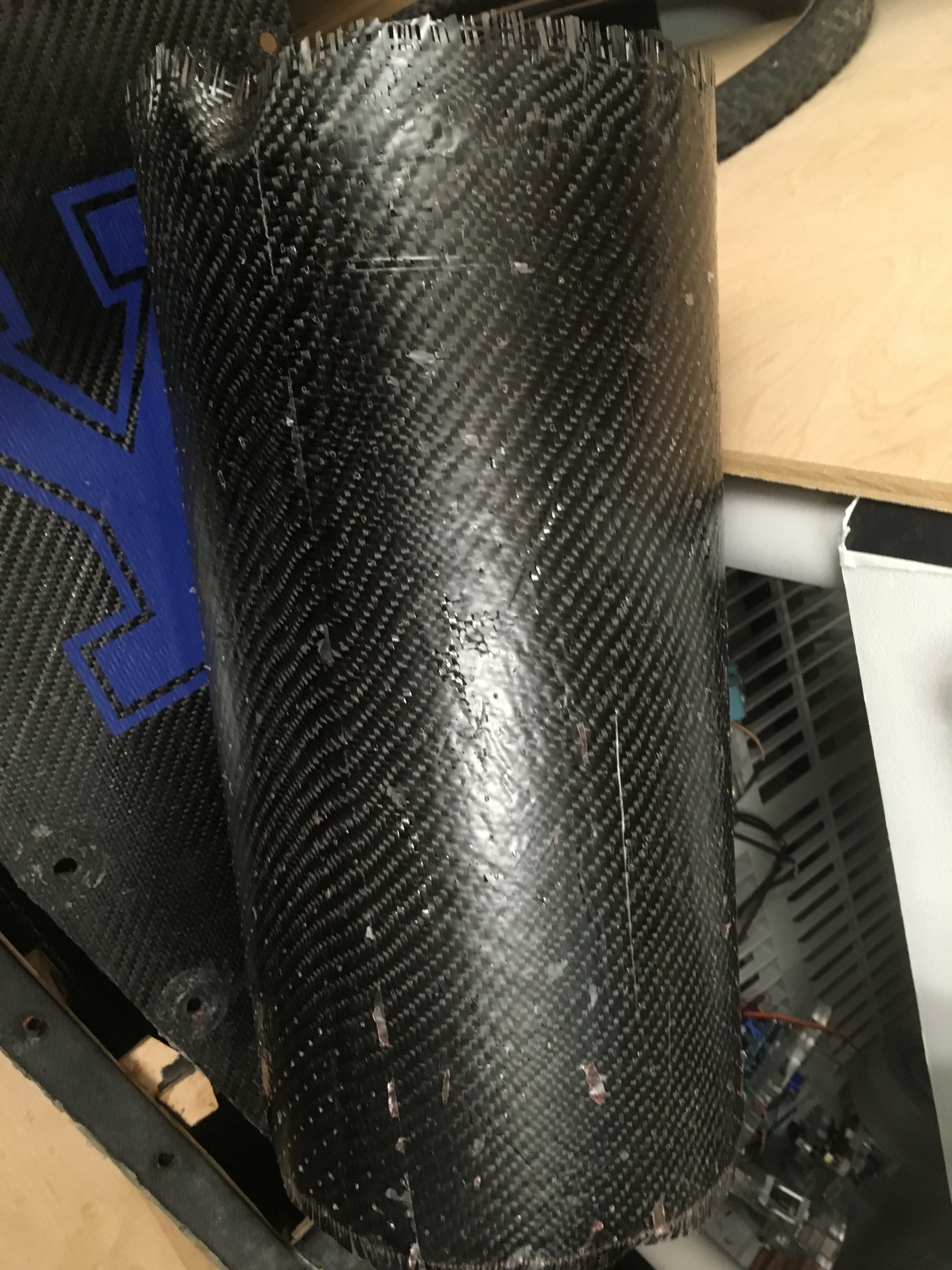
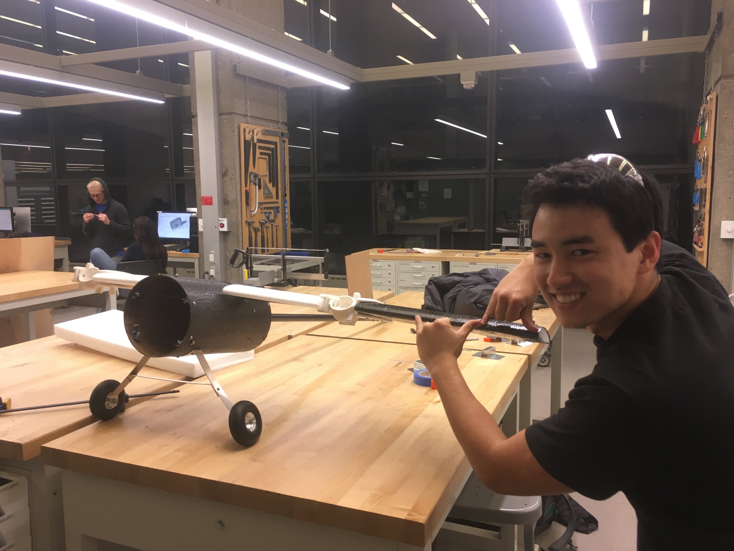
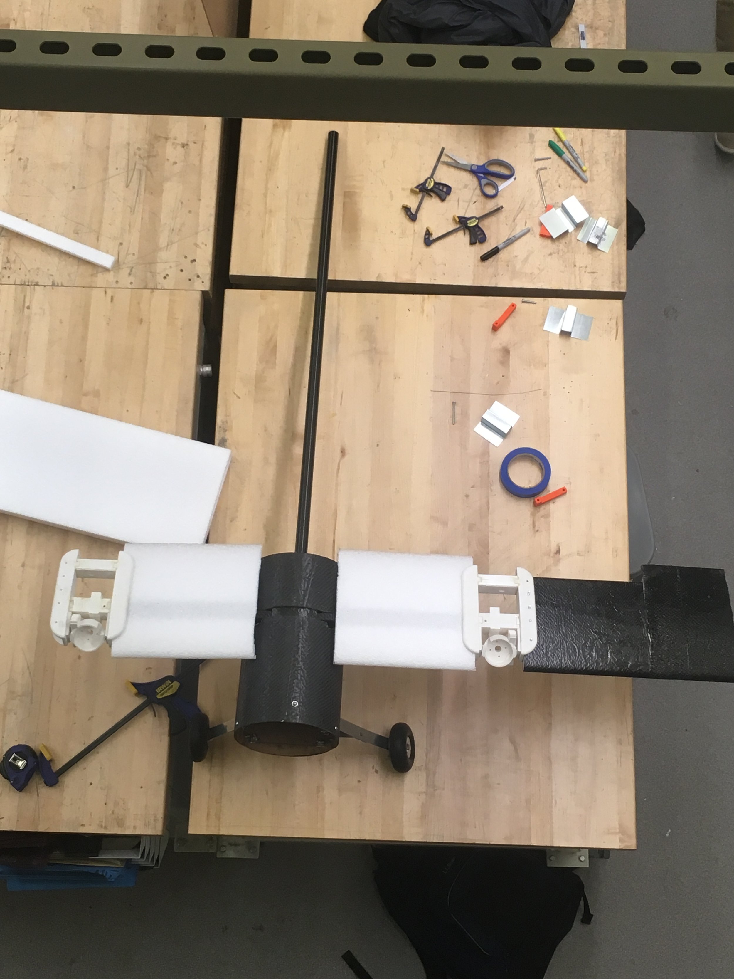
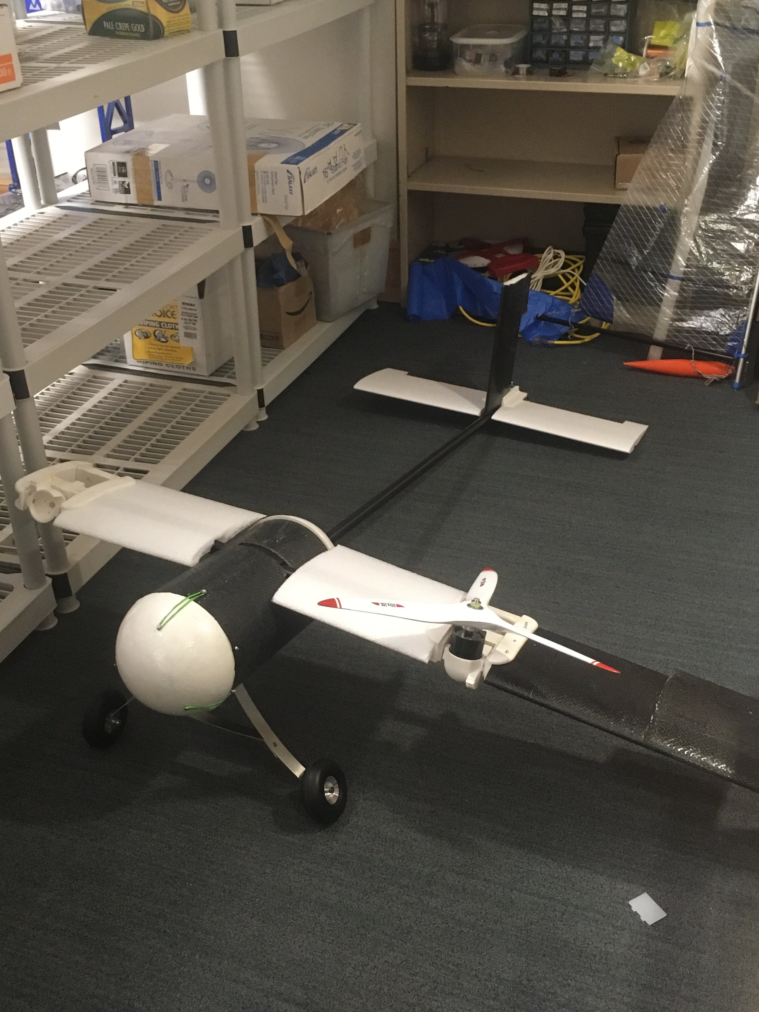
Once initial design work was completed in October, parts were ordered using funds from SEAS and the Connecticut Space Grant Consortium. The fuselage was the first composite layup in the project and served as a learning experience for the team on how to fabricate carbon fiber components. By the end of the project, most of the team was proficient in performing basic carbon fiber layups. Two shelves were built to support the electronics in the fuselage. The front and rear nosecones of the fuselage were made using expanded polystyrene hemispheres. These hemispheres were covered in a sealant then painted with epoxy resin for added rigidity. Three nails were pushed into each so that they could be elastically attached to the fuselage. The landing gear was made from sheet metal, and wheels were bought online. The wings were bought from a website called Flying Foam which custom cuts EPP and EPS foam airfoils. Some of the wings were ordered with a rectangular cutout at the bottom so that a carbon fiber strut could be placed underneath. This allowed the wings to bear the weight of the motors even while maneuvering in flight. The wings were also laid up to increase strength. A component to connect the stabilizers to the tail was designed in Solidworks and 3D printed. Each of the three stabilizers was fitted into slots in this component which attached to the carbon fiber rod. The carbon fiber rod was connected to the fuselage using two wooden disks of equal diameter (see the actual aircraft for better understanding). All the wiring for the tail control surfaces and motors was routed through the carbon fiber rod. Power for the servos was provided off of the BEC of the ESCs. Similarly to the main motors, the rear motors were mounted on a carbon fiber strut.
Perhaps the most complicated components of the aircraft were the tilt pods. They underwent multiple design iterations and were eventually 3D printed out of ABS at the School of Architecture. These parts were fitted onto the end of the central wing segment and strut and allowed for actuation of the main motors, allowing the aircraft to act as both a quadcopter and a plane. These parts also incorporated the aileron servos and were the attachment point for the outer wing segments.
The outer wings were attached using very weak 3D printed pins so that the wings could snap off the aircraft without causing more catastrophic damage in the event of a crash. During fabrication of the airframe, work continued on the software. Although the software team had been reduced to a single member, work on an initial version was completed in April.
Testing and Results
By the end of the semester, the aircraft was more than 90% complete and electromechanically capable of acting as a quadcopter. Some fabrication of control surfaces remained, and additional work in wire management and the landing forward landing gear were required. The aircraft underwent a tethered test to proved that it could output more thrust than its own weight. The aircraft left the ground with a PWM command with the duty cycle 40% of the calibrated maximum. Unfortunately, it was revealed that one of the main motors was in contact with its housing, causing friction during operation. During the final test, the heat due to friction resulted in the motor reaching a very high temperature and emitting a significant amount of smoke. The semester ended before further testing could be conducted.